
If you’re looking for a comprehensive guide to the Scytek a15 wiring diagram, you’ve come to the right place. This article will provide you with all the information you need to understand the inner workings of this advanced car security system. Whether you’re an experienced installer or a DIY enthusiast, we’ll break down the wiring diagram step by step, so you can confidently install and configure your Scytek a15 system.
Before we dive into the specifics of the wiring diagram, let’s briefly discuss what the Scytek a15 is. The Scytek a15 is a state-of-the-art car alarm and security system that offers a wide range of features to protect your vehicle from theft and other potential threats. With its advanced technology and user-friendly interface, it’s no surprise that this system has become a popular choice among car owners who prioritize safety and security.
Now, let’s take a closer look at the Scytek a15 wiring diagram. This diagram outlines the connections and configurations necessary to properly install the system in your vehicle. It includes information about the power supply, sensors, sirens, and other components that make up the Scytek a15 system. By following this diagram meticulously, you’ll be able to ensure a seamless installation process and maximize the performance of your Scytek a15 system.
Scytek a15 Wiring Diagram

The Scytek a15 is a popular car alarm and remote start system that provides security and convenience features for your vehicle. To properly install and connect the Scytek a15 system, it is important to follow the wiring diagram provided by the manufacturer.
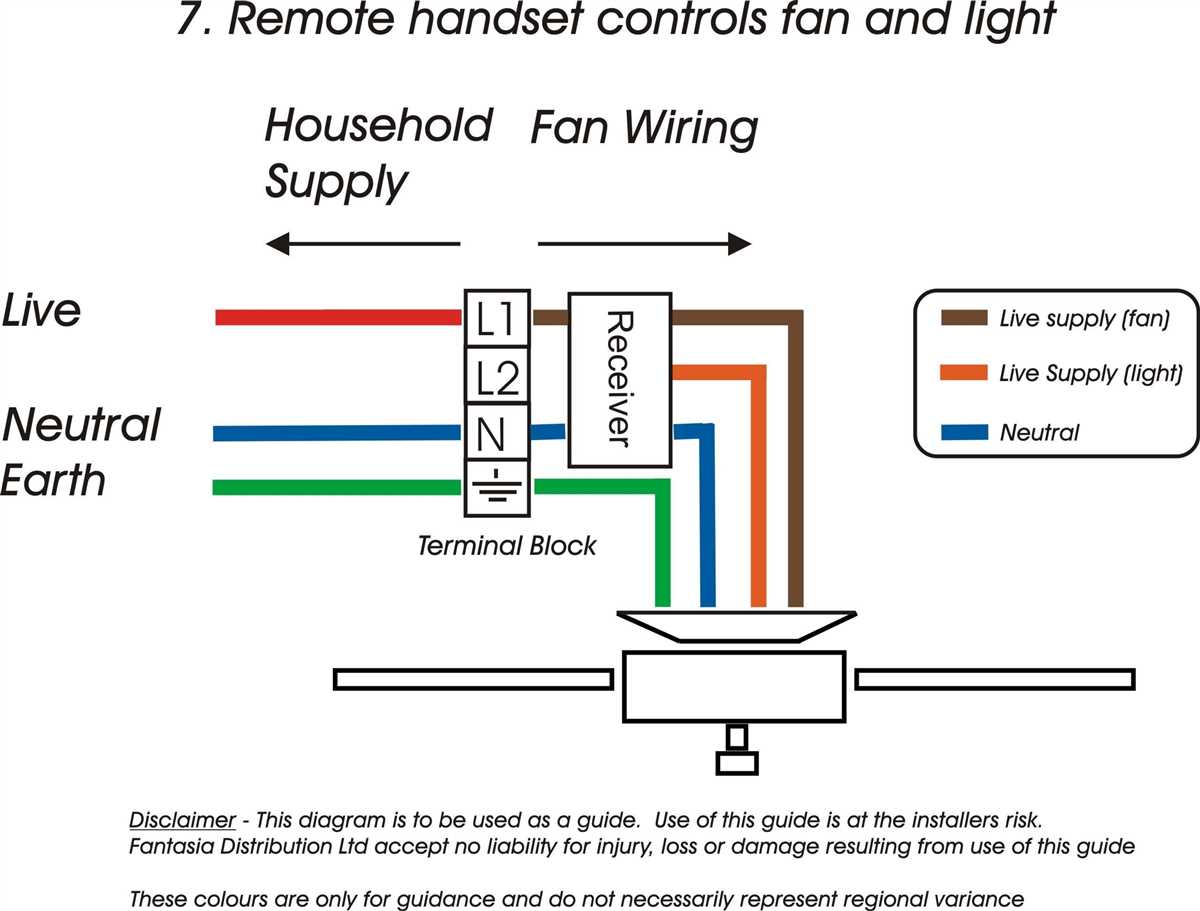
The wiring diagram for the Scytek a15 includes detailed instructions on how to connect the various components of the system, such as the control module, keyless entry module, and siren. It also includes information on how to wire the system to the vehicle’s ignition, parking lights, and other necessary connections.
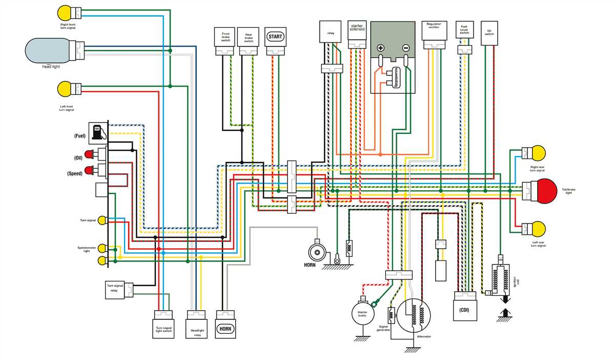
The wiring diagram typically shows the color-coded wires and their corresponding connections, making it easier to follow and ensure proper installation. It may also provide information on any additional components, such as relays or diodes, that may be required for certain features or functions of the Scytek a15 system.
Following the wiring diagram is crucial to ensure that the Scytek a15 system functions correctly and safely. Improper wiring can result in the system not working properly or potentially causing damage to the vehicle’s electrical system.
It is recommended to consult the Scytek a15’s installation manual or contact a professional installer if you are not familiar with automotive wiring and electrical systems. They can provide guidance and ensure that the Scytek a15 system is installed correctly and according to the manufacturer’s specifications.
Overall, the Scytek a15 wiring diagram is a valuable resource for installing and connecting the system properly. By following the diagram and utilizing proper wiring techniques, you can enjoy the added security and convenience that the Scytek a15 system offers for your vehicle.
What is a Scytek a15?
The Scytek a15 is a car alarm and remote start system designed to enhance the security and convenience of your vehicle. It is a popular aftermarket accessory that provides keyless entry, remote engine start, and comprehensive car protection features.
The Scytek a15 comes with a range of advanced functions, including an LCD display remote that allows you to control various aspects of your vehicle. It offers a wide range of programmable options, such as temperature sensors, auto-lock/unlock, timed start, and more. The system also incorporates high-level security features like double pulse unlock, ignition-controlled door locks, and dual-stage shock sensors.
One notable feature of the Scytek a15 is its compatibility with smartphones. With the addition of a compatible module, you can use your smartphone as a remote control for various functions of the system. This allows for greater convenience and flexibility in managing your vehicle’s security and starting functions.
The installation of the Scytek a15 usually requires professional expertise due to its complex wiring system. It is important to consult the wiring diagram and follow the instructions provided to ensure a proper installation. Correct installation is crucial for the optimal functioning of the system and to avoid any potential damage to your vehicle’s electrical system.
In summary, the Scytek a15 is a comprehensive car alarm and remote start system that offers enhanced security and convenience features. Its advanced functions, compatibility with smartphones, and professional installation requirement make it a popular choice among car owners looking to upgrade their vehicle’s security system.
Why do you need a wiring diagram?

When it comes to installing or troubleshooting electrical systems, having a wiring diagram is essential. A wiring diagram is a detailed representation of the electrical connections and components in a system. It provides a visual guide that shows how the system is wired, including the placement of wires, connections, and power sources.
One of the main reasons why you need a wiring diagram is for proper installation. Whether you are installing a new Scytek A15 car alarm system or any other electronic device, a wiring diagram helps you understand the correct connections and ensure that everything is wired correctly. It helps prevent mistakes and confusion, saving you time and effort.
Furthermore, a wiring diagram is crucial for troubleshooting. If you encounter any issues with the system, having a wiring diagram allows you to trace the electrical pathways and identify any potential problems. It helps you pinpoint the exact location of faulty connections, damaged wires, or malfunctioning components, making it easier to fix the issue.
In addition, a wiring diagram serves as a valuable reference for future modifications or upgrades. If you want to add new features or integrate additional devices into your Scytek A15 system, a wiring diagram provides a roadmap for making the necessary connections. It ensures that the new components are properly integrated into the existing system without causing any conflicts or electrical issues.
In conclusion, a wiring diagram is essential for proper installation, troubleshooting, and future modifications of electrical systems like the Scytek A15. It serves as a visual guide that helps you understand the connections and ensures that everything is wired correctly. Whether you’re a professional installer or a DIY enthusiast, having a wiring diagram is crucial for successfully working with electrical systems.
Understanding the components of a Scytek a15
The Scytek a15 is an advanced car alarm system that provides security and convenience features for your vehicle. To understand how it works, it is important to familiarize yourself with its components. Here are the key components of a Scytek a15:
Main Control Unit

The main control unit is the brain of the Scytek a15 system. It is responsible for processing signals from various sensors and controlling the different functions of the alarm system. The main control unit is typically installed in a secure location inside the vehicle.
Key Fob
The key fob is a handheld device that allows you to control the Scytek a15 system remotely. It typically features buttons for arming and disarming the alarm, as well as additional functions such as trunk release or panic mode. The key fob communicates with the main control unit via radio frequency signals.
Sensors

The Scytek a15 system utilizes various sensors to detect and monitor different aspects of your vehicle. These sensors include:
- Motion sensors: These sensors detect any movement inside or around the vehicle and trigger the alarm if unauthorized entry or tampering is detected.
- Shock sensors: These sensors detect any impact or vibrations to the vehicle, such as someone trying to break a window or force the door open.
- Door sensors: These sensors detect the opening and closing of doors, triggering the alarm if a door is opened without authorization.
- Trunk sensor: This sensor detects the opening of the trunk, providing an additional layer of security.
- Ignition sensor: This sensor detects the ignition status of the vehicle and can be used to activate or deactivate certain features of the alarm system.
Siren
The siren is an integral part of the Scytek a15 system that produces loud audible alerts when the alarm is triggered. The siren is designed to attract attention and deter potential thieves.
Wiring Harness

The wiring harness is a collection of wires and connectors that connect the different components of the Scytek a15 system. It allows for the transmission of signals and power between the main control unit, sensors, key fob, and other components.
In conclusion, understanding the components of a Scytek a15 is essential for effectively utilizing the car alarm system. The main control unit, key fob, sensors, siren, and wiring harness all work together to provide security and convenience features for your vehicle.
Step-by-step guide to wiring a Scytek a15
Wiring a Scytek a15 car alarm system can be done in a few simple steps. Before you begin, make sure you have gathered all the necessary tools and materials, including wire cutters, electrical tape, and a wiring diagram for your specific vehicle.
Step 1: Disconnect the battery
The first step in wiring the Scytek a15 is to disconnect the negative terminal of the vehicle’s battery. This is important to prevent any accidental electrical shocks or damage to the vehicle’s electrical system during the installation process.
Step 2: Locate the wiring harness
Next, locate the wiring harness that is included with the Scytek a15 car alarm system. The wiring harness will consist of different colored wires, each with a specific function, such as power, ground, ignition, and door triggers.
Step 3: Connect the power wire
Using the wiring diagram for your specific vehicle, identify the power wire in the wiring harness. This wire will usually be thick and red in color. Connect this wire to the positive terminal of the vehicle’s battery using a butt connector or solder and heat shrink tubing for a secure connection.
Step 4: Connect the ground wire
Locate the ground wire in the wiring harness, which is usually black in color. Connect this wire to a metal part of the vehicle’s chassis, such as a screw or bolt, to create a solid ground connection.
Step 5: Connect the ignition and door trigger wires
Refer to the wiring diagram to identify the ignition and door trigger wires in the wiring harness. These wires are responsible for activating the alarm when the ignition is turned on or when the doors are opened. Connect these wires to the corresponding ignition and door trigger wires in the vehicle’s wiring system.
Step 6: Test the system
After completing the wiring connections, it is important to test the Scytek a15 car alarm system to ensure that it is working properly. Reconnect the negative terminal of the vehicle’s battery and test the alarm by arming and disarming it, as well as testing the various trigger functions.
Following these step-by-step instructions will allow you to successfully wire a Scytek a15 car alarm system and enhance the security of your vehicle.
Troubleshooting common wiring issues

Wiring issues can be common when installing or troubleshooting a Scytek a15 alarm system. These issues can cause various problems, such as malfunctioning sensors, intermittent connections, or even complete system failure. It is important to effectively troubleshoot and resolve these issues to ensure the proper functioning of the alarm system. Here are some common wiring issues and possible solutions:
1. Loose or disconnected wires

One of the most common wiring issues is loose or disconnected wires. This can occur during installation or due to accidental damage. To troubleshoot this issue, start by visually inspecting the wires and connections. Make sure all wires are securely connected and properly insulated. If any wires are loose or disconnected, reattach them and secure them with electrical tape or wire connectors.
2. Incorrect wiring connections

Incorrect wiring connections can also cause problems with the alarm system. This can happen if the wires are connected to the wrong terminals or if the polarity is reversed. To troubleshoot this issue, consult the wiring diagram of the Scytek a15 alarm system and double-check the connections. Ensure that the wires are connected to the correct terminals and that the polarity is correct. If any incorrect connections are found, make the necessary corrections.
3. Damaged or worn-out wires
Over time, wires can become damaged or worn out, leading to connectivity issues. Inspect the wires for any signs of fraying, cuts, or corrosion. If any damaged wires are found, they should be replaced. Use wire strippers to remove the damaged section and attach a new wire using wire connectors.
4. Sensor placement and alignment

If the alarm system is experiencing issues with specific sensors, the placement and alignment of the sensors may be the cause. Make sure that the sensors are positioned correctly and aligned with the corresponding target areas. Adjust the placement and alignment as necessary to ensure proper sensor functionality.
By troubleshooting and resolving these common wiring issues, you can ensure the proper functioning of your Scytek a15 alarm system. Remember to always refer to the wiring diagram and follow the manufacturer’s instructions when working with the alarm system wiring.