To analyze interactions between oppositely or similarly charged particles, focus on the arrangement of vectors illustrating their influence on space. When approaching this concept, pay close attention to the direction and intensity of these vectors, which indicate the nature of force propagation from each source.
Identifying key patterns is essential: for unlike charges, vectors tend to converge at a point of attraction, while like charges exhibit divergence, forming a repulsive structure. Take note of areas where vector density increases, indicating stronger forces at work, and use this to predict particle behavior under varying conditions.
In situations with multiple sources of influence, observe the resultant vector configuration. The superposition principle will guide you in determining the overall field pattern, as individual forces combine to shape the final outcome. This is crucial when predicting how one charge will impact another in proximity.
Interaction of Charge Distributions
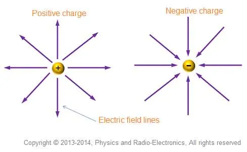
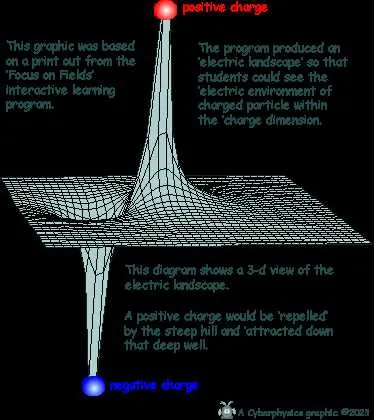
Visualize how force vectors behave in the vicinity of positive and negative point sources. Positive sources emit repulsive arrows, while negative attract the surrounding particles. Density of arrows indicates strength of the influence–closer to sources, vector density increases.
When both sources are placed close, observe curved trajectories as a result of their opposing or attracting natures. The closer the charges, the more complex the pattern becomes, with lines bending sharply near the sources.
For balanced charges, straight pathways extend from positive to negative regions. In case of unequal magnitudes, a distorted flow will occur with stronger pull in areas near the more intense source.
Key takeaway: Distance significantly impacts the strength and directionality of the resulting force vectors. Use this principle for more accurate modeling in simulations or practical applications.
Understanding Behavior of Forces Between Opposite Charges
Place one positive and one negative point of attraction close together. Force lines will originate from the positive, extending towards the negative. This creates a path of strongest influence, indicating where particles would experience maximum interaction.
Intensity of this influence increases as proximity decreases. For minimal distance, force distribution will be most concentrated, showing a curved shape connecting both points. Each trajectory represents potential paths for a charged particle within that region, influenced by both forces simultaneously.
In regions outside these influences, lines become more diffuse, indicating weaker force intensity. By altering distance between these points, the pattern changes, but the fundamental principle remains: force always travels from positive to negative. Understanding this movement allows predicting behavior under varying conditions.
Analyzing such patterns helps in optimizing configurations for applications like capacitor design or understanding molecular bonding in physics.
How to Interpret Electric Field Patterns Around Identical Charges

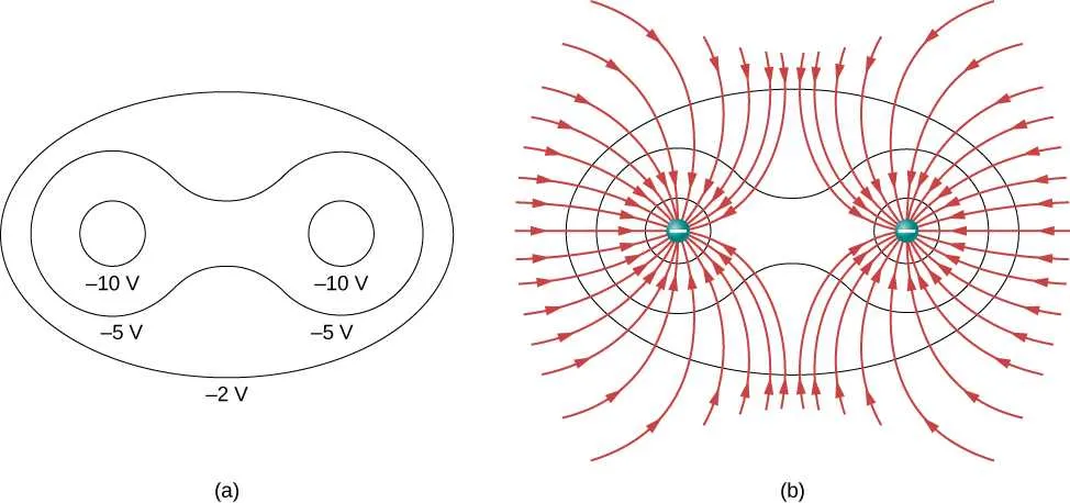
When examining patterns created by identical point sources of charge, focus on regions where forces interact. Positive and negative regions emerge where opposites attract, while like charges repel, creating a symmetry. For two like charges, expect a distinct repulsive force pointing away from both centers. Midway between them, forces cancel out, creating a zero potential point.
Pay attention to the curvature of force vectors. They radiate outward from each charge, curving toward the midpoint where the forces balance. At points farther from both sources, these vectors will gradually become parallel, reflecting weaker interactions.
In regions equidistant from both sources, assess the alignment of force vectors; they will oppose each other directly. These critical points mark locations of neutral interaction, known as saddle points, where forces are balanced but not equal in magnitude.
For greater accuracy, remember that charge magnitude impacts the spacing and strength of vectors. Larger charges create stronger, more densely packed force vectors, while smaller charges result in broader, weaker patterns. Adjust observations based on this variation for precise analysis.
Practical Applications of Electric Field Diagrams in Electrical Engineering

To enhance design accuracy in systems involving force interactions, professionals must visualize energy distributions. Here are key areas where this tool proves essential:
- Capacitor Design: Accurate placement of electrodes and insulation layers requires a clear understanding of potential differences. Visualizing force vectors aids in determining optimal spacing and material selection.
- Electromagnetic Shielding: Ensuring optimal shielding effectiveness for sensitive components depends on understanding how forces interact within materials. This allows engineers to design more efficient barriers against unwanted radiation.
- Transistor Modeling: Designing semiconductors involves assessing how particles are influenced by surrounding potentials. Force maps provide insight into current flow and behavior under different biasing conditions.
- Energy Harvesting Systems: Efficiency of devices that convert kinetic energy into electricity is influenced by external forces. These illustrations help in evaluating how well energy can be extracted from fluctuating fields in dynamic environments.
- Sensor Technology: Many sensors rely on variations in surrounding forces to detect changes. By using force patterns, engineers can optimize sensor placement and alignment to improve accuracy.
For successful implementation in any of these applications, precise simulations and real-time visualization play a critical role in avoiding inefficiencies and potential errors in component behavior.