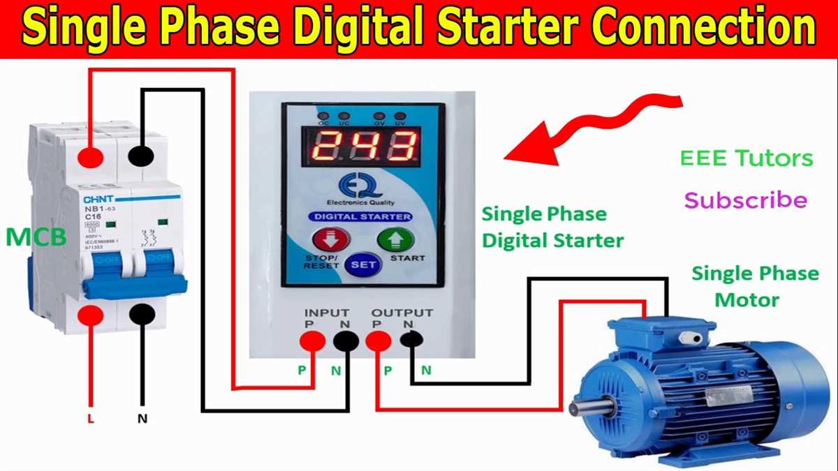
Single phase induction motors are commonly used in various applications where the availability of a three-phase power supply is not feasible or cost-effective. These motors are widely used in household appliances, small industrial equipment, and other low power applications. The wiring of a single phase induction motor is relatively simple compared to three-phase motors, but it requires careful attention to ensure proper functioning.
The wiring of a single phase induction motor consists of various components, including the main winding, start winding, run capacitor, and centrifugal switch. The main winding is responsible for producing the rotating magnetic field that drives the motor, while the start winding provides the initial torque required to start the motor. The run capacitor helps improve the efficiency and power factor of the motor, while the centrifugal switch is used to disconnect the start winding once the motor reaches its operating speed.
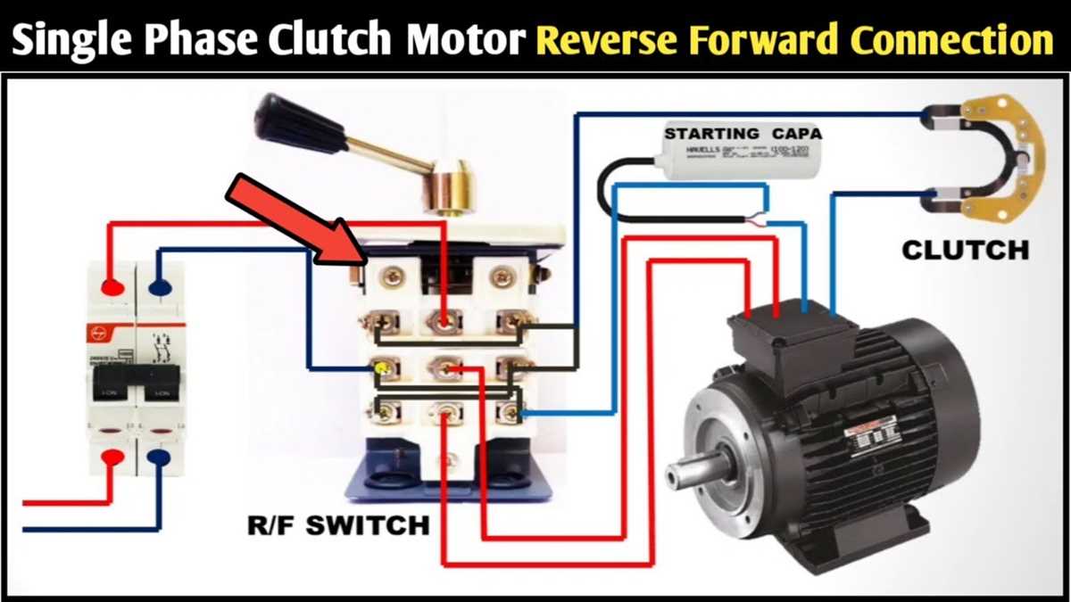
When wiring a single phase induction motor, it is crucial to follow the manufacturer’s instructions and refer to the wiring diagram provided with the motor. The wiring connections should be made using suitable cables and connectors, and the wiring should be properly insulated to prevent any electrical hazards. It is also essential to ensure that the motor is connected to the correct power supply voltage and that the motor’s rotation direction matches the intended application.
In conclusion, the wiring of a single phase induction motor is a crucial step in ensuring its proper functioning and longevity. By following the manufacturer’s instructions and paying attention to the wiring diagram, it is possible to install and wire a single phase induction motor safely and effectively.
Understanding Single Phase Induction Motor Wiring
Single phase induction motors are commonly used in residential and small-scale industrial applications. They are widely used due to their simplicity, affordability, and ease of maintenance. Understanding the wiring of these motors is essential for proper installation and operation.
The wiring of a single phase induction motor typically consists of several key components. These include the main power supply, starting capacitor, start winding, main winding, centrifugal switch, and the motor itself. Each of these components plays a vital role in the motor’s operation and should be connected correctly for the motor to function properly.
The main power supply is usually a single-phase AC source, typically from a household outlet. This power supply is connected to the motor’s terminals through a switch or a control device. It provides the necessary electrical energy for the motor to operate.
The starting capacitor is an additional component connected in parallel with the main winding. It helps the motor to develop a rotating magnetic field during startup, which is essential for motor performance. The start winding is connected in series with the starting capacitor and is responsible for creating a second magnetic field that interacts with the main winding, causing the motor to start rotating.
As the motor reaches a certain speed, the centrifugal switch disconnects the starting capacitor and the start winding, ensuring that they do not interfere with the motor’s operation. This switch is typically controlled by centrifugal force, activated when the motor reaches its designed speed.
In summary, understanding the wiring of a single phase induction motor involves knowing the role and connection of each component: the main power supply, starting capacitor, start winding, main winding, and centrifugal switch. Careful attention to these connections ensures the motor’s proper operation and longevity.
Basics of Single Phase Induction Motor Operation
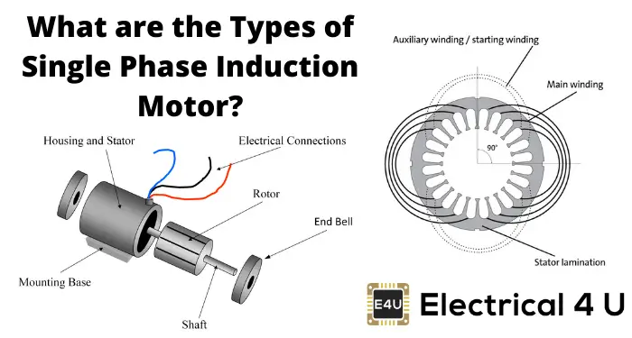
The single phase induction motor is a type of electric motor that is commonly used in various applications such as household appliances, small power tools, and pumps. It is called a “single phase” motor because it operates with a single phase power supply, unlike three phase motors which require a three phase power supply.
The operation of a single phase induction motor is based on the principle of electromagnetic induction. When an AC voltage is applied to the motor’s stator winding, it creates a rotating magnetic field. This rotating magnetic field interacts with the rotor, which is made of a series of conductive bars or coils, inducing an electric current in the rotor. The interaction between the rotating magnetic field and the induced current in the rotor creates a torque, causing the rotor to rotate.
The single phase induction motor has two main types: the split-phase motor and the capacitor-start motor. The split-phase motor uses a starting winding and a running winding to create the rotating magnetic field. The starting winding is disconnected from the circuit once the motor reaches a certain speed, while the running winding continues to provide the torque required to maintain the motor’s rotation.
The capacitor-start motor, on the other hand, uses a capacitor in conjunction with a starting winding to create a phase shift in the current flowing through the starting winding. This phase shift creates a rotating magnetic field and helps the motor to start rotating in the desired direction. Once the motor reaches a certain speed, a centrifugal switch disconnects the starting winding and the capacitor from the circuit.
Summary:
- The single phase induction motor operates with a single phase power supply.
- It works on the principle of electromagnetic induction.
- There are two main types of single phase induction motors: split-phase and capacitor-start motors.
- The split-phase motor uses a starting winding and a running winding.
- The capacitor-start motor uses a capacitor and a starting winding to create a phase shift in the current.
Components of a Single Phase Induction Motor
A single phase induction motor consists of several key components that work together to generate rotational motion. These components include:
- Stator: The stator is the stationary part of the motor and consists of a laminated iron core with evenly spaced slots. The stator winding is placed in these slots and is responsible for producing the magnetic field necessary for motor operation.
- Rotor: The rotor is the rotating part of the motor and is either squirrel cage type or wound type. The rotor winding is short-circuited and provides the necessary torque to start and run the motor.
- Start and run windings: Single phase induction motors typically have two windings – the start winding and the run winding. The start winding is made of smaller wire size and higher resistance, while the run winding is made of larger wire size and lower resistance. These windings create a rotating magnetic field and help in motor starting and running.
- Centrifugal switch: The centrifugal switch is a mechanism that is used to disconnect the start winding from the power supply once the motor reaches a certain speed. This switch helps to prevent the start winding from overheating during continuous operation.
- Bearings: Bearings are used to support the rotating shaft of the motor and reduce friction. The motor typically has two bearings – one at the drive end and one at the non-drive end.
- Capacitor: Some single phase induction motors also require a capacitor for starting purposes. The capacitor provides additional torque during starting and helps in overcoming the inherent lack of a rotating magnetic field in a single phase system.
These components work together to create the necessary magnetic fields and torque to start and run a single phase induction motor. Understanding the role of each component is crucial in troubleshooting and repairing motor-related issues.
Types of Single Phase Induction Motor Wiring
Single phase induction motors are widely used for various applications due to their simplicity and cost-effectiveness. These motors are commonly found in household appliances, small machinery, and HVAC systems. There are several types of wiring configurations that can be used for single phase induction motors, each with its own advantages and disadvantages.
Split-Phase Induction Motor Wiring
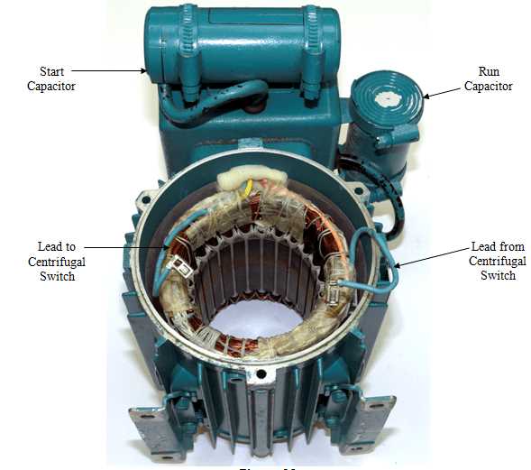
Split-phase induction motor wiring is the most common type of wiring used for single phase motors. This wiring configuration uses a special type of winding called a start winding to create a rotating magnetic field. The start winding is connected to the power source through a starting capacitor, which helps to provide the necessary torque for starting the motor. Once the motor reaches a certain speed, the start winding is disconnected from the power source, and the motor continues to run on the main winding. Split-phase induction motors are simple and reliable, but they have lower starting torque compared to other wiring configurations.
Capacitor-Start Induction Motor Wiring
Capacitor-start induction motor wiring is another commonly used configuration for single phase motors. This wiring configuration also uses a start winding to create a rotating magnetic field. However, instead of a starting capacitor, a start capacitor is used to provide the necessary torque during startup. Once the motor reaches a certain speed, a switch called a centrifugal switch disconnects the start winding and start capacitor from the power source. The motor then continues to run on the main winding. Capacitor-start motors have higher starting torque compared to split-phase motors, making them suitable for applications that require higher torque at startup.
Capacitor-Start Capacitor-Run Induction Motor Wiring
Capacitor-start capacitor-run induction motor wiring is a more advanced configuration that provides even higher starting torque. This wiring configuration uses two capacitors, a start capacitor and a run capacitor. The start capacitor provides the initial torque during startup, while the run capacitor helps to improve the motor’s performance during running operation. Once the motor reaches a certain speed, a centrifugal switch disconnects the start capacitor, leaving only the run capacitor in the circuit. This wiring configuration offers the highest starting torque and is commonly used in applications that require a high torque at startup, such as air compressors and pumps.
Overall, the choice of single phase induction motor wiring depends on the specific requirements of the application. Split-phase, capacitor-start, and capacitor-start capacitor-run configurations offer different levels of starting torque and performance, allowing for the motor to be tailored to the specific needs of the application.
Wiring Diagram for Capacitor Start Induction Motors
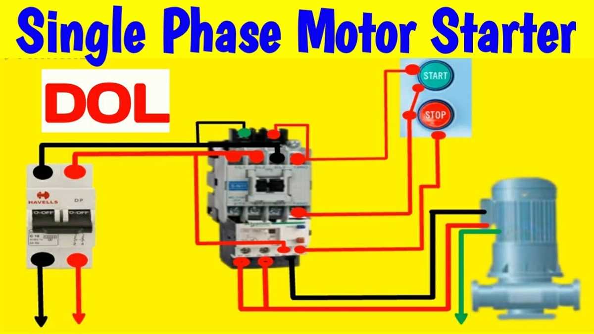
A capacitor start induction motor is a type of single-phase motor that is designed to provide high starting torque while also maintaining efficient performance. This type of motor is commonly used in applications where a high starting torque is required, such as in air compressors, refrigerators, and vacuum cleaners.
The wiring diagram for a capacitor start induction motor typically consists of three main components: the motor, the capacitor, and the switch. The motor is connected to the power supply through the switch, which is used to start and stop the motor. The capacitor is connected in series with the start winding of the motor, providing the necessary phase shift to create a rotating magnetic field.
The wiring diagram usually depicts the connections between these components using standardized symbols. The motor is represented by a circle with two lines coming out of it, representing the two windings of the motor. The capacitor is represented by a curved line with a plus and minus sign, indicating its polarity. The switch is represented by a line with a small gap in the middle, indicating its ability to open and close the circuit.
When the switch is closed, the motor is connected to the power supply and the start winding is energized. The capacitor provides the necessary phase shift to create a rotating magnetic field, which in turn produces the high starting torque. Once the motor reaches a certain speed, the switch opens, disconnecting the capacitor from the circuit and allowing the motor to run on the main winding alone.
Summary:
- A capacitor start induction motor is designed to provide high starting torque.
- The wiring diagram includes the motor, capacitor, and switch.
- The capacitor is connected in series with the start winding of the motor.
- The motor is represented by a circle, the capacitor by a curved line, and the switch by a gap in the line.
- The capacitor provides the necessary phase shift for high starting torque.
- Once the motor reaches a certain speed, the capacitor is disconnected from the circuit.
Wiring Diagram for Capacitor Run Induction Motors
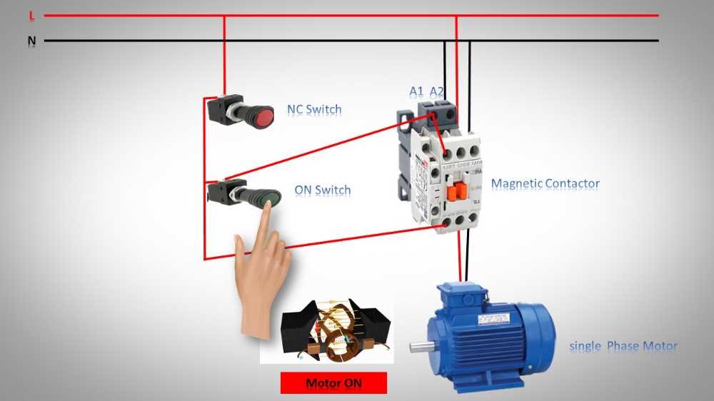
A capacitor run induction motor is a type of single phase induction motor that uses a capacitor to start and run the motor. This type of motor is commonly used in applications where high starting torque is required, such as in air conditioning units, compressors, and certain types of pumps.
The wiring diagram for a capacitor run induction motor typically includes three main components: the motor itself, the capacitor, and the power supply. The motor has two windings: the main winding and the auxiliary winding. The main winding is connected directly to the power supply, while the auxiliary winding is connected in series with the capacitor.
The wiring diagram usually shows the connections between these components using symbols or labels. The power supply is typically represented by a series of lines or a voltage source symbol. The main winding is represented by a coil symbol, while the auxiliary winding is represented by a coil symbol with a smaller size or different shape. The capacitor is usually represented by a parallel or series capacitor symbol.
- The power supply is connected to one end of the main winding, and the other end of the main winding is connected to the common terminal of the motor.
- The other end of the auxiliary winding is connected to one end of the capacitor, and the other end of the capacitor is connected to the other terminal of the motor.
- In some wiring diagrams, a centrifugal switch is also included. This switch is used to disconnect the capacitor and the auxiliary winding once the motor reaches a certain speed. This prevents the auxiliary winding from overheating during normal operation.
It is important to follow the wiring diagram carefully when wiring a capacitor run induction motor to ensure proper operation and to prevent damage to the motor components. Consulting the motor’s manufacturer or the wiring diagram provided with the motor is recommended to ensure accurate and safe wiring.
Common Troubleshooting Tips for Single Phase Induction Motor Wiring
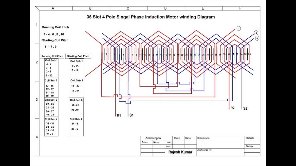
Wiring issues can cause various problems with single phase induction motors. Here are some common troubleshooting tips to help you identify and resolve these issues:
1. Check the power supply
Make sure that the motor is receiving the correct voltage and frequency from the power supply. Any deviations from the required specifications can cause motor malfunctions. Use a multimeter to measure the voltage and frequency at the motor terminals, and compare them to the motor’s specifications.
2. Inspect the wiring connections
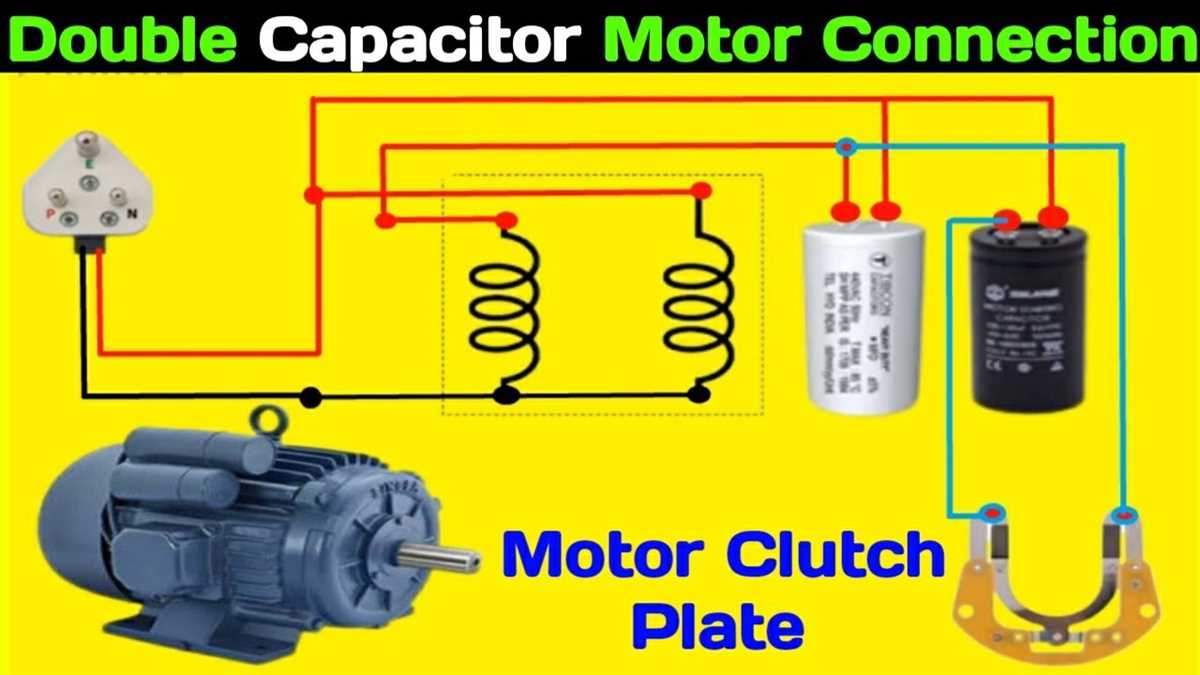
Examine all the wiring connections, including the line connections, start winding connections, and run winding connections. Ensure that the connections are secure and tight. Loose or faulty connections can cause overheating, motor inefficiency, or complete motor failure.
3. Test the capacitors
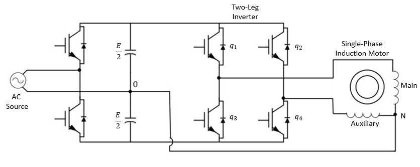
Motor capacitors are critical components in single phase induction motors. Use a capacitance meter to test the capacitance of the start and run capacitors. A faulty capacitor can cause the motor to start slowly or struggle to start at all. Replace any defective capacitors.
4. Check for motor overload
Motor overload can occur when the motor is subjected to excessive load or when the motor is undersized for the intended application. Check the motor’s nameplate to verify the rated full load current. If the motor is consistently tripping the overload protection, it may be necessary to replace or upgrade the motor.
5. Inspect the motor windings
Visually inspect the motor windings for any signs of damage, such as burnt or discolored insulation. Use a megger or insulation resistance tester to measure the insulation resistance between the motor windings and the motor frame. Low insulation resistance values indicate a potential short circuit or ground fault, which should be addressed immediately.
6. Consult a professional
If you have exhausted all troubleshooting options and are unable to identify or resolve the issue, it is recommended to consult a professional electrician or motor technician. They have the expertise and specialized tools to diagnose and repair motor wiring problems safely and effectively.
By following these troubleshooting tips, you can effectively identify and resolve common wiring issues with single phase induction motors. Regular maintenance and periodic inspections can help prevent many motor problems and ensure optimal motor performance.