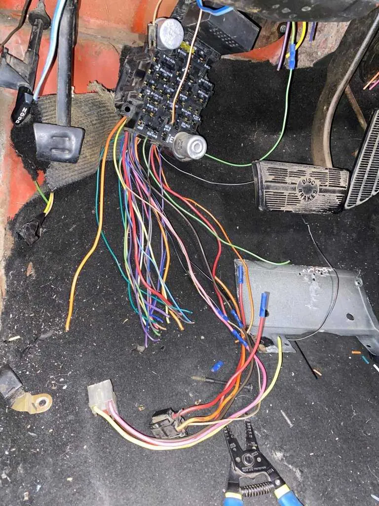
For proper electrical connection of the key-operated control unit in Chevrolet models, focus on the correct identification of each terminal on the ignition mechanism. The starter wire must link directly to the solenoid terminal to ensure engine activation without delay. Misrouting this connection often leads to starting failures or electrical shorts.
Pin assignments vary slightly depending on the production year, so verify the label color codes and terminal positions against factory schematics. The accessory circuit wire powers auxiliary systems when the key is in the run position and should be isolated from the main power feed to avoid backfeed issues.
Grounding points on the assembly must have solid metal contact without corrosion to maintain stable operation of electronic ignition components. Use dielectric grease on connectors to prevent oxidation and maintain signal integrity over time.
Testing continuity between the battery source and the starter engagement line before final assembly reduces troubleshooting time. A digital multimeter is recommended for this verification, with key positions cycled to confirm correct circuit activation and deactivation.
Ignition Assembly Electrical Connection Layout for Chevrolet
Locate the main connector harness behind the steering assembly to identify the power feed, accessory circuit, and starter relay wires. The primary feed is typically a thick red wire supplying constant battery voltage.
Accessory output wires are usually colored brown or yellow and provide power to dashboard instruments when the key is in the ON position. Confirm continuity with a multimeter before proceeding.
The starter activation line can be found as a smaller gauge wire, often purple or pink, which energizes the starter relay during engine cranking.
Ground connections are crucial; ensure the black or brown ground wire is securely attached to the vehicle frame to prevent intermittent faults.
For models from the 1990s onward, the anti-theft immobilizer wiring integrates a data bus line, commonly white with a colored tracer, requiring careful handling to avoid disabling vehicle security functions.
Always refer to the factory service manual for exact pin assignments as variations exist between model years and trims. Use proper connectors and avoid splicing without sealed crimps to maintain circuit integrity.
Identifying and understanding wire colors and functions in Chevy ignition switch
Follow the color code strictly: The key harness uses specific hues to denote circuit roles. A red wire usually delivers constant battery power, feeding essential systems even when the vehicle is off. The brown wire often corresponds to accessory power, energizing radios and auxiliary components when the key is turned to the accessory position.
Yellow wires serve as the main ignition feed, activating critical engine circuits. A pink wire typically handles the starter relay trigger, sending current to engage the starter motor during engine start.
Black or black with white stripe represents ground or chassis connection, crucial for circuit completion. Orange wires often relate to illumination, controlling dash light brightness.
Verify wire functions by consulting vehicle-specific service manuals, as slight variations may occur between models and years. Use a multimeter to confirm voltage presence and continuity before replacing or modifying any connectors.
Maintain clear labeling on all leads to avoid confusion during repairs or diagnostics. Applying dielectric grease to connectors reduces corrosion and enhances signal reliability.
Step-by-step process to connect the key start circuit on a Chevy
- Disconnect the vehicle’s battery to prevent shorts or accidental sparks.
- Remove the protective cover surrounding the ignition assembly to access internal connectors.
- Identify the main power feed wire–typically a red cable supplying 12V constant power from the battery.
- Locate the accessory output lead, usually brown or orange, which energizes vehicle accessories when the key is turned to the ON position.
- Find the starter solenoid wire, often purple or yellow, which engages the starter motor when the key is in the START position.
- Connect the ground wire if present; some setups require a chassis ground for proper circuit completion.
- Match and join each cable by color coding or pin location to the corresponding terminal on the ignition assembly socket.
- Secure all connectors firmly, ensuring no loose contacts or exposed metal that could cause shorts.
- Reinstall any covers or panels removed to access the connector housing.
- Reconnect the battery and test each key position:
- OFF – no power to accessories or starter.
- ACC – accessories receive power.
- ON – vehicle systems activate.
- START – starter motor engages.
Following this sequence minimizes risk of electrical faults and guarantees proper function of the ignition system circuit.
Troubleshooting common electrical connection problems in Chevy’s control assembly
Start by checking the main connector for corrosion or bent terminals, as these cause intermittent power loss. Use a multimeter to verify voltage continuity between the battery feed and the output terminals during key engagement. A voltage drop exceeding 0.5 volts indicates resistance due to poor contacts.
Inspect the ground cable for tightness and absence of rust at the chassis attachment point. Faulty grounding often leads to failure in signal transmission to the starter relay. Clean and retighten connections as necessary.
Look for damaged insulation or pinched cables along the steering shaft harness that could cause shorts or open circuits. Pay special attention to areas near moving parts where wires may have been rubbed through.
Replace any brittle or cracked terminals within the connector housing. Plastic degradation often leads to loose contacts, causing intermittent electrical interruptions.
Test the actuator mechanism with a continuity tester to ensure internal contacts engage properly under mechanical activation. Failure here may mimic wiring faults but requires component replacement.
Confirm that all auxiliary circuits, such as accessory power feeds, maintain correct voltage levels during operation. Dropouts in these circuits often indicate partial contact failure within the control interface.
Use dielectric grease on connectors to prevent moisture ingress, which is a common cause of corrosion and short circuits in older vehicles.