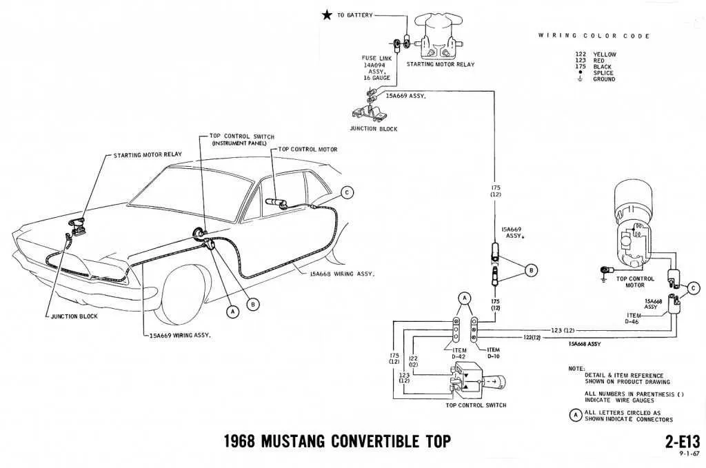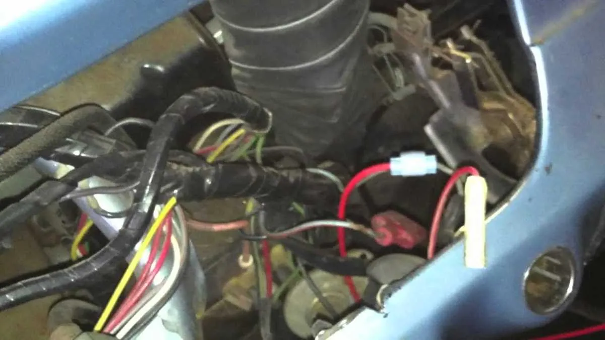
Start by checking the fuse block under the dash on the driver’s side. It’s the central point for circuits like headlights, ignition, and instrument panel. If lights or gauges aren’t functioning, inspect connections here first.
Color codes are essential: black with yellow stripe powers the headlamps, green-red feeds the brake lights, and red-white manages the starter solenoid. Any deviation could indicate a short or corrosion at the connector terminals.
The ignition switch routes power through a red-green wire to the coil and starter relay. If the engine won’t crank, test continuity through this path before replacing components.
Behind the cluster, the printed circuit board connects gauges to senders via plug-in harnesses. Oil pressure uses a white-red lead, while the fuel level relies on a yellow wire. Replace brittle insulation immediately to avoid arcing.
Tail light assemblies receive voltage from a single green wire split through the rear harness. Ground continuity is equally critical–verify chassis contact near the trunk latch or rear valance mounting points.
Fuse Box Layout and Circuit Connections

Start by inspecting the fuse panel located beneath the driver’s side dashboard. Verify that the power distribution includes circuits for headlights, ignition, instrument lights, and accessories. Each terminal should be labeled: IGN, ACC, BATT, and LPS, correlating to ignition, accessories, battery, and lighting power.
Ensure the headlamp switch receives direct power from the battery terminal via a red wire and outputs through blue-red (dimmer) and black-yellow (tail lamp) lines. Use a multimeter to test continuity from the dimmer switch to the sealed beam units on both high and low beam paths.
Check the firewall plug for corrosion or looseness, especially where the engine harness routes through to connect starter solenoid, oil pressure sender (white-red), and coil positive (red-green). Confirm the generator warning lamp circuit (yellow-black) links cleanly to the voltage regulator.
Instrument cluster illumination typically runs through blue wires with red tracers; verify grounding points at the dash frame to avoid dim or flickering gauges. For brake light operation, trace the green wire from the pedal switch to rear lamp assemblies, ensuring the feed from the turn signal switch remains uninterrupted.
How to Locate and Identify Key Components in the 1966 Mustang Wiring Diagram

Start by finding the fuse box–typically illustrated near the lower left quadrant of most schematics. It controls circuits for lights, ignition, and accessories. Look for rectangular symbols labeled with amperage values (e.g., 14A, 20A).
Next, trace the power distribution lines from the battery terminal, often shown as a thick red or black line branching to multiple relays and switches. Identify the voltage regulator by locating the component connected between the alternator and battery, usually marked with three terminals: “F,” “S,” and “A.”
Locate the ignition switch circuit, often centrally positioned, linking to coil, starter solenoid, and neutral safety switch. Key identifiers include terminal codes such as “I,” “S,” and “R.”
To pinpoint lighting components, follow the headlamp and taillight paths, typically extending from a central lighting switch. These are often tied to dimmer and floor switch indicators, marked by foot-activated symbols.
Gauge cluster connections appear grouped together, leading to oil pressure, fuel level, speedometer, and temperature sensors. Look for color-coded lines–often yellow, green, or blue–with terminal notations like “S” for sender and “G” for ground.
Troubleshooting Common Electrical Issues Using the 1966 Mustang Wiring Layout
Start by checking the fuse box located under the dash near the driver’s side. Blown fuses often indicate a short circuit or overloaded component. Use a multimeter to test continuity across each fuse before replacing any.
- Headlights not working: Inspect the headlamp switch and dimmer switch connections. Follow the black-yellow and red-black wires leading from the switches to the front light assemblies. Look for signs of corrosion or frayed insulation.
- Starter not engaging: Verify the red-blue lead from the ignition switch to the neutral safety switch. Ensure the clutch or shifter is properly positioned. Check the solenoid on the inner fender–poor ground can prevent engagement.
- Turn signals malfunctioning: Locate the flasher unit behind the glove box. Confirm that the orange-blue and light blue-white wires from the directional stalk have solid contact. A faulty ground at the rear light sockets is a common issue.
- Gauge cluster dead: Trace the voltage regulator behind the instrument panel. The black-green feed should deliver 5V regulated power. Inspect the printed circuit for burnt traces or loose connectors.
- Battery draining overnight: With the engine off, measure current draw at the negative terminal. Anything over 50mA suggests a parasitic load. Pull one fuse at a time to isolate the circuit, often tied to glove box or trunk lamps staying on.
For intermittent issues, flex harnesses near the steering column and under the carpet. Pinched or brittle insulation may cause shorts that only appear under certain conditions. Always refer to original color codes and connector positions when testing continuity.
Steps to Rewire a 1966 Mustang Using a Factory-Style Wiring Harness
Disconnect the battery before any disassembly to prevent shorts or electrical hazards. Remove both terminals and secure them away from the engine bay.
Label all existing connectors using masking tape and a permanent marker. Mark each plug by its function to ensure accurate reconnection during installation.
Remove the old loom systematically, starting at the firewall. Trace each route through the cabin, engine bay, and trunk. Use a trim removal tool to avoid damaging clips and grommets.
Lay out the replacement harness on a clean surface. Match the new connectors to your labeled originals. Inspect all sockets and verify that wire colors match OEM specifications for lights, gauges, ignition, and accessories.
Feed the new assembly through the bulkhead grommet and secure each branch with original-style clips. Begin routing toward the fuse panel, steering column, and headlight buckets.
Connect circuits one at a time, starting with the charging system, ignition switch, and lighting controls. Use a multimeter to test continuity and verify ground points before finalizing connections.
Install the fuse block in the factory location using original mounting hardware. Confirm fuses match amperage ratings from the technical manual.
Secure all branches with cloth loom tape or split tubing to replicate the stock look. Avoid plastic zip ties where visible for authenticity.
Reconnect the battery only after double-checking all splices, grounds, and terminal torque. Test each system individually–turn signals, brake lights, horn, heater fan, and gauges.