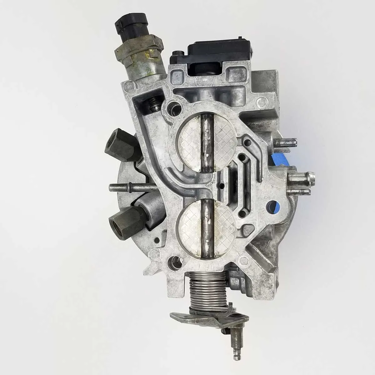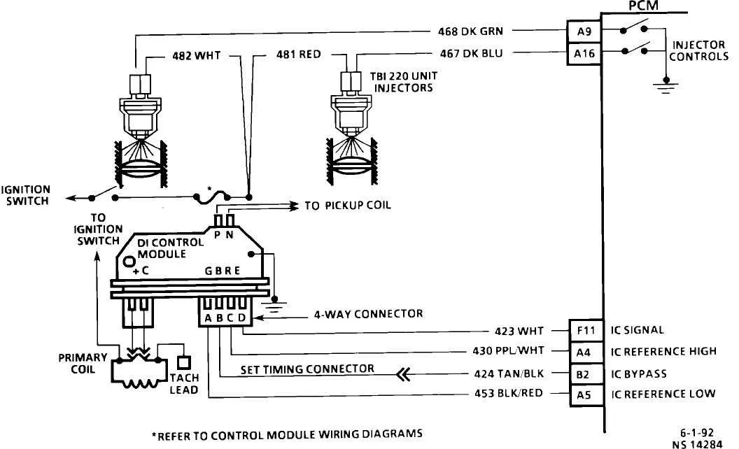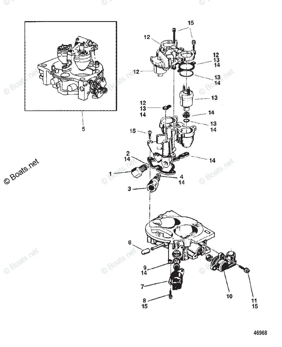
When troubleshooting issues related to the air intake in your engine, one of the first things to check is the component that controls the airflow into the engine. A clear understanding of this part and its connection to other systems is essential for effective repairs. The diagram for this part provides a detailed look at its structure and how it interfaces with sensors and other mechanisms within the engine. Referencing a well-detailed visual representation will help you identify components like the intake valve and the position sensor.
Check the connections thoroughly. Ensure that all parts are properly secured and free from obstruction. A malfunctioning system may cause erratic engine behavior such as stalling or poor acceleration. Pay attention to the seals and gaskets to prevent air leaks, which can lead to performance issues and inefficient fuel consumption.
Position sensors play a crucial role in regulating airflow and ensuring smooth engine performance. By referencing a detailed illustration, you can identify potential problems with these sensors and take corrective action. Proper understanding of this system is key to diagnosing and addressing issues effectively, minimizing repair time and cost.
Understanding the Air Intake Valve Assembly Layout
Start by identifying the key components: the air intake valve, sensors, and the linkage that controls air flow. Pay special attention to the actuator mechanism, which regulates the opening and closing of the valve based on engine demand.
Ensure the air intake valve is connected to the engine’s intake manifold properly. Misalignment can cause poor air-fuel mixture and affect engine performance. Inspect the sensor wiring for any signs of wear or corrosion. Faulty connections can lead to inaccurate readings, which will impact fuel efficiency and throttle response.
The linkage system should be checked for smooth operation. Any resistance or irregularities in movement could indicate a need for lubrication or replacement. Regular maintenance of the actuator ensures proper communication between the engine control unit and the air valve.
Refer to the specific vehicle manual for the correct torque values when reassembling parts. Tightening the valve components too much can damage the gaskets, while too little pressure might cause air leaks.
Understanding the Components of a Fuel-Air Control Valve System

To maintain optimal engine performance, it is crucial to understand the components that regulate air intake and fuel delivery. The key parts involved in this system include:
- Air Intake Valve – This regulates the airflow entering the engine, controlled by a motor or vacuum system that adjusts the valve’s opening based on engine needs.
- Motorized Actuator – Positioned to control the air intake opening, it responds to signals from the engine’s ECU (Engine Control Unit) to adjust airflow as required.
- Position Sensor – Monitors the position of the intake valve, sending feedback to the ECU to ensure the correct amount of air is being supplied.
- Idle Air Control Valve – This component adjusts the idle speed by controlling the amount of air that bypasses the main valve when the engine is idling, maintaining stable operation.
- Gasket Seal – Ensures proper sealing between the system and the intake manifold, preventing leaks that could affect air-to-fuel ratios.
Regular inspection and maintenance of these components are essential for smooth engine operation. Pay close attention to the actuator, as failure to respond to ECU signals can cause erratic engine performance.
How to Identify Common Issues in Intake Manifold and Airflow Control Systems

Look for vacuum leaks around seals and gaskets, as they can cause erratic engine performance. Examine the linkage for wear or misalignment, which can prevent smooth airflow regulation. Check for signs of dirt buildup in the airflow path, as this can restrict air intake and affect the engine’s response.
Verify that the sensor connections are clean and undamaged. Faulty sensors can lead to incorrect air-fuel mixture adjustments, causing poor engine operation. Pay attention to the wiring for signs of corrosion or fraying, which can cause electrical issues or complete failure of the control system.
Inspect the actuator mechanism for proper movement. A stuck or sluggish actuator will not adjust the airflow properly, leading to idle fluctuations or stalling. If any components appear cracked or brittle, they should be replaced immediately to maintain system integrity.
Step-by-Step Guide to Interpreting a Fuel Air Intake System Layout
Start by identifying the key components: intake manifold, airflow sensor, fuel injectors, and actuator. These parts are typically arranged in a sequence that determines air and fuel mixture delivery. A close inspection of each connection point ensures correct flow and functionality.
The airflow sensor plays a crucial role in measuring incoming air, while the actuator adjusts the air flow according to the engine’s needs. The injectors must be understood in terms of their placement and relationship to the sensor and actuator for proper calibration.
| Component | Function |
|---|---|
| Airflow Sensor | Measures air intake volume and communicates with the ECU to regulate air flow. |
| Fuel Injectors | Sprays fuel into the intake air stream at the right pressure and timing for combustion. |
| Actuator | Controls the opening and closing of the air intake valve based on engine requirements. |
| Intake Manifold | Distributes air evenly to each cylinder of the engine. |
After identifying the components, trace the connections, noting whether they are direct or through sensors. Check for any potential wear points, especially around connectors and seals. Use a multimeter to verify electrical integrity of sensor wiring.
Ensure the airflow paths are not obstructed. Follow the layout to verify that each part is aligned and functions in sync with others. Cross-check all diagnostic data with manufacturer specifications for accurate readings and performance.