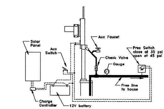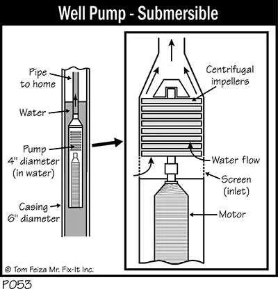
To effectively extract groundwater, it’s essential to comprehend the layout of an underground water extraction system. This system typically includes key components such as a motor, suction pipe, and the intake valve. Each part plays a crucial role in drawing water from below the surface to the desired location.
Proper installation and maintenance of these components directly impact the efficiency of the extraction process. The motor, located at the surface, powers the mechanism that lifts the water. It is vital that this motor operates at the correct power level to match the depth and volume of water required.
The suction pipe must be free from blockages and maintain an adequate diameter to allow a smooth flow of water. Any obstruction in the pipe can result in reduced flow and increased strain on the motor. Ensuring that the intake valve is positioned correctly within the water source will prevent sediment and debris from entering the system, prolonging the lifespan of the equipment.
Regular checks and service on each component should be scheduled to avoid unexpected breakdowns. In particular, ensure that seals and connections are secure to prevent leaks that can waste both water and energy.
Components of a Water Extraction System

To properly understand how a water lifting mechanism operates, it is essential to focus on the key elements involved in the extraction process. Each part has a specific role in ensuring the efficient transfer of water from underground sources to the surface.
- Motor: The motor is responsible for driving the entire system. It powers the mechanism that facilitates fluid movement.
- Impeller: The impeller creates pressure to move the liquid through the pipes, enabling its transfer from depth to surface.
- Drive Shaft: This connects the motor to the impeller, transmitting rotational force to ensure the impeller operates effectively.
- Pipe Assembly: The pipe system carries water to the surface. It is designed to handle both the pressure and flow rate required for optimal performance.
- Foot Valve: Positioned at the bottom, it ensures that water does not flow back down, maintaining consistent pressure during operation.
- Check Valve: This component prevents backflow, ensuring that the system operates without losing efficiency or pressure.
Each part must be maintained regularly to prevent blockages and wear. Routine checks on the motor, pipe integrity, and impeller functionality can significantly extend the lifespan of the setup.
Understanding the Components of a Water Extraction System
The motor serves as the primary driver of the water retrieval mechanism, converting electrical energy into mechanical force. It is crucial to select a motor with adequate horsepower to match the required flow rate and depth of extraction. Ensure it is weatherproof and suited to environmental conditions to prevent damage from moisture or debris.
The suction pipe directs the water from the source to the surface. Proper sizing of this pipe minimizes energy losses and prevents blockages, ensuring an efficient flow rate. Opt for corrosion-resistant materials such as stainless steel for longevity and durability.
The pressure switch controls the operation of the system, activating the motor when water levels drop below a predetermined threshold and deactivating it once the desired pressure is reached. A well-calibrated switch reduces wear and tear on components, ensuring consistent performance.
The check valve prevents water from flowing back into the source when the system is off, preserving the integrity of the water delivery process. Install it as close to the motor as possible to avoid water loss during inactive periods.
The storage tank stores water once it is extracted. Choose a tank with sufficient capacity to meet daily usage needs while avoiding frequent cycling of the system. Insulate the tank if it is exposed to freezing temperatures to prevent damage to pipes.
The control panel manages the system’s operational settings, including pressure, flow rate, and power settings. A reliable panel is key to maintaining the efficiency of the system, with features that allow for easy monitoring and adjustments based on usage patterns.
How to Interpret a Water Extraction System Blueprint for Installation
Start by identifying the key components shown in the layout: the intake, discharge, power source, and control system. Each element should be positioned accurately to ensure proper functionality. The intake is typically shown as the entry point for water, while the discharge path will direct water to the storage or filtration system.
Review the power and control unit sections, focusing on electrical connections and operational switches. Ensure all connections are correctly placed in accordance with the system’s power requirements. Verify that any safety mechanisms, like pressure switches or flow regulators, are properly installed as indicated in the plan.
Pay attention to the measurements provided, including pipe sizes, distance from the water source, and depth of the intake. These dimensions are critical to ensuring that the system functions at optimal efficiency. Any variation in size or placement can cause performance issues or system failure.
Next, check for the inclusion of auxiliary components such as valves, filters, or check valves. Their proper placement is essential for smooth operation, and any omission or misplacement could result in inefficiencies or damage to the system.
Lastly, always verify that the materials listed, such as pipe types, connectors, and seals, are compatible with the expected environmental conditions. This ensures long-term durability and prevents system leaks or failures.
Common Issues in Submersible System Diagrams and Troubleshooting Tips
Check the power source first if the water source isn’t reaching the expected pressure. A malfunctioning electrical connection can disrupt flow. Inspect the fuse box or circuit breaker to ensure proper current is being supplied. If everything is intact, test the wiring for continuity using a multimeter to detect potential shorts or breaks.
If the motor is running but there’s insufficient water flow, examine the intake screen for blockages. Debris can obstruct the system and cause low yield. Also, ensure that the check valve is functioning correctly to prevent backflow, which can interfere with normal operation.
For low pressure, it’s important to verify the setting of the pressure switch. If it’s improperly adjusted, the system might fail to activate or turn off prematurely. Cleaning or replacing a worn-out switch could resolve the issue.
Noisy operation typically points to a mechanical fault. Check for air bubbles or cavitation in the intake. Ensure that the system components are tightly sealed and check for any damaged seals. Additionally, verify the alignment of the pump shaft to avoid misalignment that can cause excessive noise and wear.
For a unit that doesn’t start at all, test the capacitor if the system uses one. A damaged capacitor can prevent the motor from starting. Replacing it could restore normal operation. If the motor hums but doesn’t rotate, the impeller might be seized due to debris or mineral buildup.
Finally, corrosion is a common issue in metal parts. Regularly inspect exposed components and replace any rusted or corroded parts promptly to avoid further damage and ensure long-term reliability.