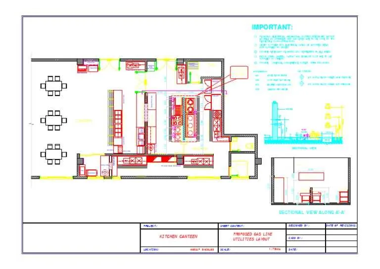
Begin with a dedicated header line feeding each dryer individually. This approach simplifies pressure balancing, facilitates maintenance, and minimizes the risk of backflow contamination. Use rigid metallic conduits with threaded joints for durability and code compliance. Avoid flexible connectors unless specifically approved for fixed installations.
Branch lines must not exceed manufacturer-specified lengths to maintain appliance efficiency. Calculate total equivalent length, including fittings, and size appropriately based on BTU requirements. For typical dryers, expect 75,000–225,000 BTU/h input; ensure supply lines are rated accordingly. Use a pressure drop chart tailored to the specific energy source in use–most often natural methane or propane derivatives.
Incorporate shut-off valves ahead of each unit and ensure sediment traps are installed directly before inlets. This prevents debris from damaging internal components. Ventilation must comply with ASHRAE standards to prevent accumulation of combustion byproducts. Isolation of appliance feeds with union joints is essential for rapid replacement or inspection without system-wide depressurization.
Secure all runs with appropriate hangers spaced according to local code–typically every 6 feet for horizontal sections. Vertical drops should include drip legs to collect condensation. Consider future expansion: leave capped tees at strategic intervals to accommodate new machinery without disruption.
Efficient Fuel Line Configuration for High-Load Laundry Facilities
Start with a dedicated manifold connected to a 2″ steel supply line rated for 2 PSI, then branch off using 1¼” or 1½” runs depending on appliance BTU load. Maintain consistent pressure by installing a regulator at each drop line feeding dryers, typically reducing to 11″ WC for compatibility with most units.
Use black iron or corrugated stainless tubing (CSST) where code allows, ensuring bonding in accordance with NFPA 54. Route distribution lines overhead with a minimum clearance of 6″ from combustibles, supporting pipe every 6 feet horizontally and every floor level vertically.
Reference the table below for appropriate pipe sizing based on total appliance demand and distance from the meter:
| Total BTU Load | Distance (ft) | Pipe Diameter |
|---|---|---|
| 400,000 | 50 | 1¼” |
| 600,000 | 75 | 1½” |
| 800,000 | 100 | 2″ |
Install shut-off valves within 6 feet of each appliance. Conduct pressure drop testing before operation, using a manometer to verify line integrity at 10 PSI for at least 15 minutes. Integrate sediment traps on all appliance connections to prevent debris damage.
Determining Pipe Sizing Requirements for Multiple Gas Dryers
Start by identifying the total BTU load from all dryers. For example, ten units rated at 35,000 BTU/h each will require a line capable of supplying 350,000 BTU/h.
Measure the longest run from the meter to the farthest appliance, including any branches. Use this distance when consulting sizing tables (e.g., NFPA 54) to ensure proper flow at peak demand.
For black iron systems at 0.5″ WC pressure drop, a 2″ diameter line handles approximately 395,000 BTU/h over 100 feet. For longer runs or higher loads, increase diameter accordingly to avoid pressure loss.
Include demand from other equipment sharing the same main. Size the trunk line to handle the combined total, then branch accordingly with appropriate reductions. Each segment must meet or exceed demand downstream.
Use dedicated regulators for pressure balancing if appliances require different supply conditions. Avoid undersized tees or elbows that can restrict flow. Keep bends to a minimum and support all sections to prevent stress and vibration.
Configuring Gas Meter and Regulator Placement for High-Demand Systems

Install the primary metering unit within 3 feet of the main utility entry point to minimize pressure drop and facilitate service access. Use a meter rated for at least 125% of the peak BTU load to prevent undersizing during simultaneous equipment operation.
Position pressure control devices downstream of the meter with a minimum of 12 inches of straight pipe between connections to ensure stable flow characteristics. For systems exceeding 2,000,000 BTU/hr, employ a two-stage regulation setup: a high-pressure regulator at the entry and a line regulator near the manifold.
Mount regulators at a height that allows unobstructed manual adjustment and inspection, typically 4 to 5 feet above finished grade. Include vent piping to the exterior for all regulators with internal relief, maintaining a minimum slope of 1/4 inch per foot away from the device.
Avoid installing meters or control assemblies above dryers or in heat-intensive zones; exposure above 120°F reduces lifespan and accuracy. Maintain at least 36 inches clearance from potential ignition sources, per NFPA 54 guidelines.
Secure all components to a fixed surface with vibration-dampening brackets, especially in high-throughput operations, to reduce mechanical stress. Incorporate unions or flanged connections on both sides of the regulator to streamline maintenance procedures.
Routing and Labeling Gas Lines According to Local Safety Codes
Install all conduits with a minimum clearance of 6 inches from electrical wiring and 12 inches from ventilation ducts to prevent interference and heat accumulation. Follow the shortest practical path while avoiding structural obstructions and high-traffic zones to reduce risk of accidental damage.
- Use ANSI Z535.1-compliant color codes: yellow for fuel transport lines, with black text indicating contents and flow direction.
- Apply markers at intervals not exceeding 25 feet in exposed areas, and every 10 feet in concealed or complex routing zones.
- Labels must appear at entry and exit points, junctions, shutoff valves, and where lines pass through walls or floors.
- All identifiers must withstand temperatures up to 150°F and remain legible in high-humidity conditions.
- Secure all routes with approved hangers rated for 1.5 times the line weight, spaced no more than 4 feet apart for horizontal runs and 6 feet for vertical sections.
- Use dielectric unions when transitioning between dissimilar metals to prevent galvanic corrosion.
- Submit all routing plans for inspection and approval by the authority having jurisdiction (AHJ) prior to installation.
Noncompliance with Chapter 4 of the Uniform Mechanical Code or NFPA 54 may result in failed inspections or immediate shutdown orders. Always document modifications with date-stamped as-built drawings.