
UML (Unified Modeling Language) is a standardized modeling language used to visualize, specify, construct, and document software systems. It is a powerful tool for software engineers and system architects to communicate and design complex systems. One of the key aspects of UML is its syntax, which defines the rules and symbols used to express different elements of a system.
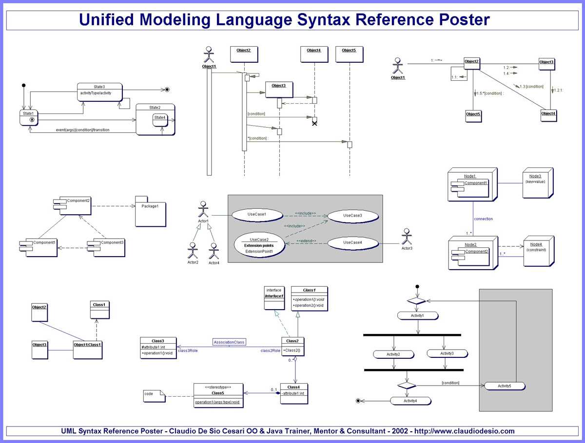
The UML diagram syntax is based on a set of standardized symbols, called UML diagrams, which represent different aspects of a system. These diagrams include class diagrams, use case diagrams, activity diagrams, and many others. Each diagram type has its own set of symbols and rules to represent specific elements and relationships.
For example, in a class diagram, classes are represented as rectangles with the class name written inside, and attributes and methods are represented as smaller rectangles connected to the class rectangle. Relationships between classes, such as associations, inheritances, and dependencies, are represented by arrows connecting the related elements.
The UML diagram syntax also includes rules for representing different types of relationships, such as aggregation, composition, and generalization. These relationships are expressed through the use of specific symbols and annotations, which help to clarify the nature of the relationship between different elements.
UML Diagram Syntax: A Comprehensive Guide for Beginners
UML (Unified Modeling Language) is a standardized visual language used for modeling and designing software systems. UML diagrams provide a graphical representation of the different aspects of a system, including its structure, behavior, and interactions. Understanding the syntax of UML diagrams is essential for beginners who want to effectively communicate and document their software designs.
One of the key elements in UML diagram syntax is the use of different types of diagrams to represent different aspects of a system. The most commonly used UML diagrams include class diagrams, which depict the static structure of the system, and sequence diagrams, which illustrate the dynamic interactions between different objects in the system. Other types of UML diagrams include activity diagrams, use case diagrams, and state machine diagrams, each serving a specific purpose in the modeling process.
Class diagrams are used to represent the static structure of a system, showing the classes, attributes, and relationships between different objects. Classes are represented as rectangles, with their attributes listed below the class name and their methods listed below the attributes. Relationships between classes, such as associations, generalizations, and aggregations, are depicted using lines with specific symbols and annotations.
Sequence diagrams are used to depict the dynamic interactions between objects in a system over time. They show the sequence of messages exchanged between objects, along with the lifelines representing the different objects involved in the interaction. Messages are represented as arrows, with labels indicating the type of message and the parameters passed. Lifelines are represented as vertical lines, showing the lifespan of an object during the interaction.
Activity diagrams are used to represent the flow of activities or processes within a system. They consist of nodes representing actions or decisions, connected by arrows representing the flow of control. Actions can be represented as atomic activities or more complex sub-activities. Decisions are represented as diamond-shaped nodes, with multiple outgoing arrows representing different possible paths based on different conditions.
In addition to these diagrams, UML also provides a range of other diagram types, such as use case diagrams for modeling system requirements, state machine diagrams for modeling the behavior of an object, and component diagrams for modeling the dependencies between different components in a system. Mastering the syntax and usage of these different types of UML diagrams is crucial for effectively communicating and documenting software designs.
What is UML and Why Should You Use It?
UML stands for Unified Modeling Language, and it is a standardized visual modeling language that is used in software development to represent systems, processes, and structures. UML provides a way to communicate and document complex software designs in a clear and concise manner, making it easier for developers, stakeholders, and team members to understand and collaborate on a project.
UML diagrams consist of various graphical elements such as classes, objects, interfaces, components, and relationships, which are used to represent different aspects of a system or software design. These diagrams can be classified into several types such as class diagrams, use case diagrams, sequence diagrams, activity diagrams, and more, each serving a specific purpose and providing insights into different aspects of the system.
There are several reasons why you should consider using UML in your software development projects:
- Clarity and Communication: UML provides a common language and notation that can be easily understood by software developers, project managers, and stakeholders. It helps in communicating complex ideas and design concepts in a visual and intuitive way, reducing ambiguity and misunderstandings.
- Visualization and Analysis: UML diagrams provide a visual representation of the system or software design, allowing developers to analyze and understand the relationships, dependencies, and interactions between different components. It helps in identifying potential issues, gaps, or improvements in the design early in the development process.
- Documentation and Maintenance: UML diagrams serve as a documentation tool that captures the essence of the software design. They can be used as a reference for future developers, aiding in system maintenance, refactoring, and troubleshooting. UML diagrams also facilitate knowledge sharing and transfer within teams.
- Standardization and Reusability: UML is a standardized language with well-defined syntax and semantics. Its standardized notation makes it easier to communicate and collaborate across different teams and organizations. UML diagrams can also serve as reusable artifacts that can be leveraged in other projects to save time and effort.
In summary, UML is a powerful visual modeling language that offers numerous benefits in software development. By using UML, you can enhance communication, improve understanding and analysis of software designs, facilitate documentation and maintenance, and promote standardization and reusability. It is a valuable tool for any software development project, helping to streamline the development process and produce high-quality software.
Understanding the Basic Elements of UML Diagram Syntax
UML (Unified Modeling Language) is widely used in software development and system design to visually represent the structure, behavior, and relationships of a system. UML diagrams provide a standardized way of communicating complex concepts and ideas to stakeholders.
When working with UML diagrams, it is important to understand the basic elements of UML diagram syntax. These elements include classes, objects, associations, attributes, operations, and inheritance.
Classes
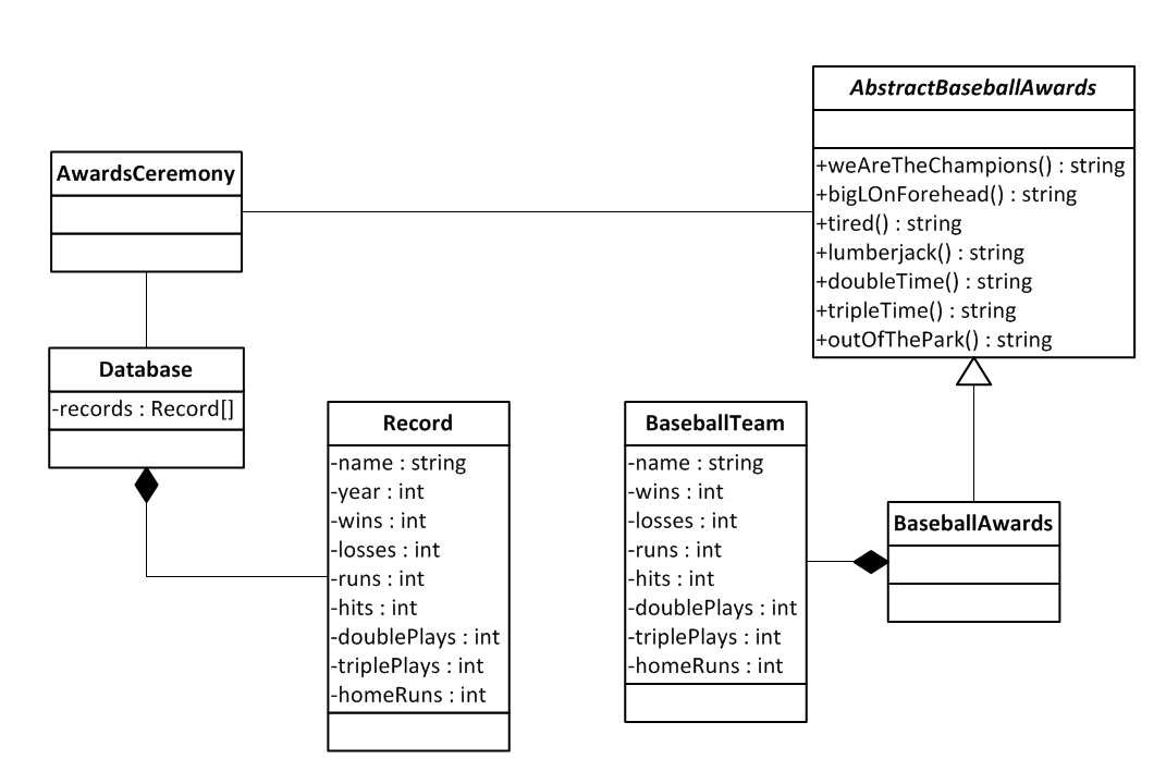
A class represents a blueprint or template for creating objects in a system. It defines the properties and behavior of similar objects. In UML diagrams, classes are represented by rectangles with three compartments: the top compartment contains the class name, the middle compartment contains the attributes (properties) of the class, and the bottom compartment contains the operations (methods) of the class.
Objects
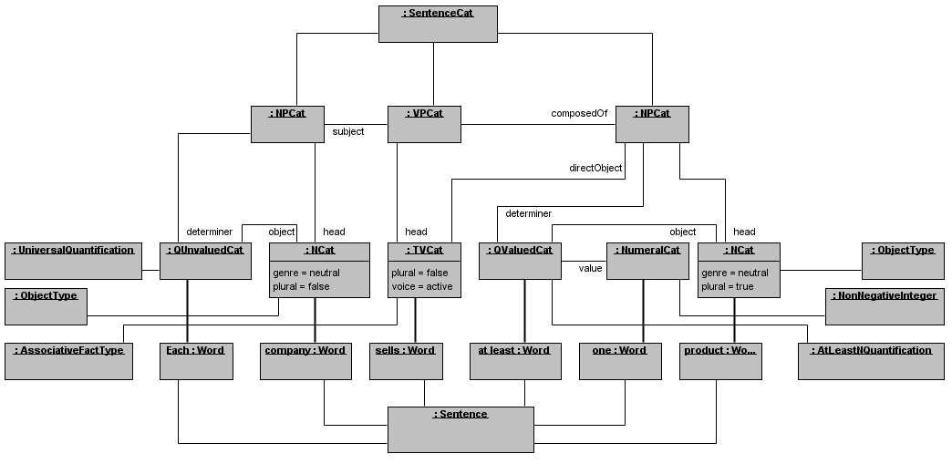
Objects are instances of classes. They represent specific instances of the class and have their own unique state and behavior. In UML diagrams, objects are depicted as rectangles with underlined names. They are connected to their respective classes through association lines.
Associations
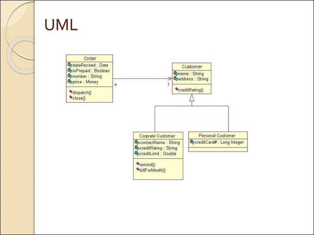
Associations represent the relationships between classes and objects. They describe how objects interact with each other and can have different multiplicities, such as one-to-one, one-to-many, and many-to-many. Associations are depicted as lines connecting classes or objects, with optional arrows indicating the direction of the relationship.
Attributes
Attributes define the characteristics or properties of a class. They represent the data that is associated with an object of the class. In UML diagrams, attributes are listed in the middle compartment of the class rectangle and are typically represented with a name and a type.
Operations
Operations (also known as methods) define the behavior or actions that a class can perform. They represent the functions or procedures associated with an object of the class. In UML diagrams, operations are listed in the bottom compartment of the class rectangle and are typically represented with a name, parameters, and a return type.
Inheritance
Inheritance is a fundamental concept in object-oriented programming that allows classes to inherit the properties and behavior of other classes. It represents an “is-a” relationship between classes, where a subclass inherits from a superclass. In UML diagrams, inheritance is depicted using an arrow with an open triangle pointing to the superclass.
By understanding these basic elements of UML diagram syntax, software developers and system designers can effectively communicate the design and structure of a system, ensuring clear understanding and collaboration among stakeholders.
Types of UML Diagrams and When to Use Them
UML (Unified Modeling Language) diagrams are a standardized visual representation for designing and documenting software systems. There are several types of UML diagrams, each serving a different purpose and capturing specific aspects of a system. Knowing when to use each type of diagram is crucial for effective software development and communication among stakeholders.
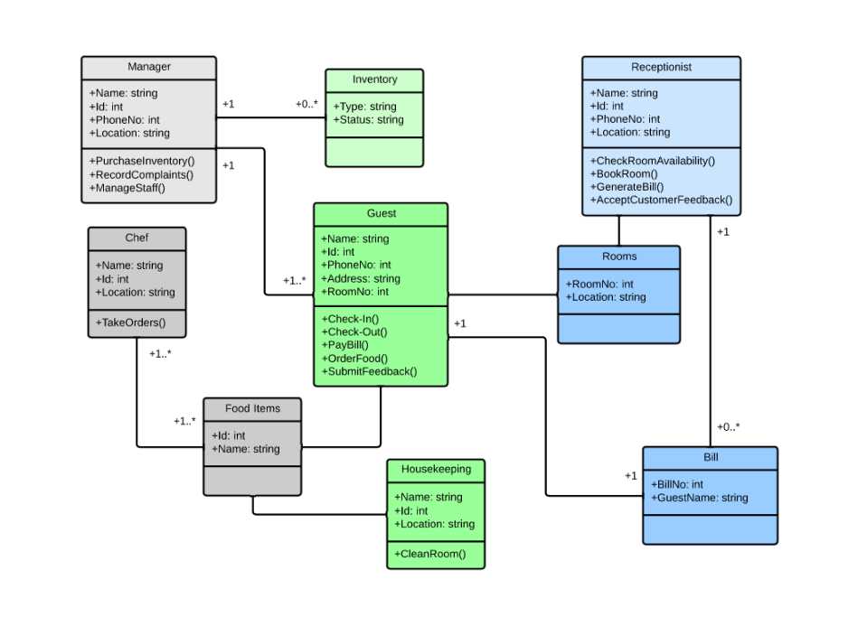
1. Class Diagram: The class diagram is used to represent the structure and relationships among classes in a system. It provides a high-level view of the objects, their attributes, and the operations they can perform. Class diagrams are particularly useful during the initial phases of system design to outline the main components and their relationships.
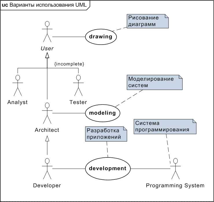
2. Use Case Diagram: Use case diagrams depict the interactions between a system and its users or external entities. They illustrate the various use cases or functionalities that the system offers, along with the actors involved. Use case diagrams are valuable for capturing the functional requirements of a system and identifying the different roles and responsibilities of its users.
3. Sequence Diagram: Sequence diagrams focus on the chronological order of messages exchanged between objects or actors. They show the flow of control and the temporal dependencies between different components of a system. Sequence diagrams are especially useful for capturing the dynamic behavior and interactions of a system, making them ideal for analyzing and optimizing system performance.
4. Activity Diagram: Activity diagrams visualize the workflow or business processes within a system. They represent the steps, decision points, and parallel activities involved in achieving a particular goal. Activity diagrams are highly beneficial for modeling complex processes, identifying bottlenecks, and ensuring efficient execution of tasks.
- 5. Statechart Diagram: Statechart diagrams represent the different states that a system or object can be in and the transitions between those states. They show how the system responds to events and changes its behavior over time. Statechart diagrams are particularly useful for modeling the behavior of complex systems or objects with multiple states.
- 6. Component Diagram: Component diagrams illustrate the physical or logical components of a system and their dependencies. They show how different components interact to achieve a specific functionality. Component diagrams are helpful for understanding the overall architecture of a system and ensuring modularity and reusability in the design.
Overall, each UML diagram serves a specific purpose in system design and development. Choosing the appropriate diagram type depends on the information or aspect of the system that needs to be represented. By utilizing the right UML diagrams at the right time, software professionals can effectively communicate, analyze, and design complex systems.
Step-by-Step Guide on Creating UML Diagrams
UML, or Unified Modeling Language, is a visual representation of a software system using a set of diagrams. It provides an efficient way to communicate and document the structure, behavior, and interactions of a system. Creating UML diagrams can be a complex process, but by following a step-by-step guide, you can easily create accurate and comprehensive diagrams.
Step 1: Identify the purpose of the UML diagram
Before creating a UML diagram, it is important to determine its purpose. UML diagrams can be used for different purposes, such as understanding system requirements, designing system architecture, or documenting system behavior. By identifying the purpose, you can select the appropriate UML diagram type and determine what elements should be included in the diagram.
Step 2: Choose the right UML diagram type
There are several types of UML diagrams, each serving a specific purpose. Some common types include class diagrams, use case diagrams, sequence diagrams, and activity diagrams. Depending on the purpose of your diagram, choose the appropriate type that best represents the system or process you are modeling.
Step 3: Identify the elements to include in the diagram
Once you have determined the purpose and selected the diagram type, identify the elements that need to be included in the diagram. For example, in a class diagram, you would include classes, attributes, and relationships between classes. In a use case diagram, you would include actors, use cases, and relationships between them. Identifying the elements beforehand will help you organize and structure your diagram effectively.
Step 4: Arrange the elements in the diagram
After identifying the elements, arrange them in the diagram to visualize the relationships and interactions. Use appropriate symbols and connectors to represent the elements and their connections. Ensure that the diagram is easy to understand and navigate by following a logical and intuitive layout.
Step 5: Add details and annotations
Once the basic structure of the diagram is created, add additional details and annotations to enhance its clarity and comprehensiveness. Add labels, descriptions, and notes to explain the purpose and functionality of each element. Use colors, fonts, and formatting to highlight important information and improve readability.
Step 6: Validate and review the diagram
Before finalizing the diagram, validate its accuracy and completeness. Review the diagram carefully to ensure that all elements and relationships are correctly represented. Verify that the diagram effectively communicates the intended information and meets the requirements of its purpose.
Step 7: Share and collaborate on the diagram
Once the UML diagram is finalized, share it with relevant stakeholders and collaborate on it if needed. UML diagrams are meant to be shared and discussed among team members, developers, and designers. Use appropriate tools or platforms to share the diagram and gather feedback and suggestions for improvement.
By following these steps, you can create UML diagrams that accurately represent your software system and effectively communicate its structure and behavior.
Tips and Best Practices for Writing Clean and Effective UML Diagrams
UML diagrams are widely used in software development to visualize and communicate the structure, behavior, and relationships within a system. To ensure clarity and maintainability, it is essential to follow some best practices when creating UML diagrams. This article provides tips to help you write clean and effective UML diagrams.
1. Use Clear and Concise Labels: Labels on UML diagram elements should be clear, concise, and meaningful. Avoid using unclear or ambiguous terms that can lead to confusion. Use proper naming conventions and ensure consistency across your diagrams.
2. Maintain Consistent Visuals: Consistency in the visual representation of elements is crucial for readability. Use the same shapes, colors, and line styles for similar elements across different diagrams. This helps users understand the relationships and patterns more easily.
3. Simplify Complex Diagrams: If a diagram becomes too complex, it can be difficult to understand and maintain. Break down complex diagrams into smaller ones or use hierarchical structures to represent different levels of detail. Avoid overcrowding and use grouping elements to organize related elements.
4. Highlight Key Relationships: Identify and emphasize the most important relationships in your UML diagrams. Use different line styles or colors to distinguish between different types of relationships, such as inheritance, association, or aggregation. This helps viewers quickly grasp the structure and connections within the system.
5. Document Assumptions and Constraints: UML diagrams should not only depict the system’s structure and behavior but also capture any assumptions or constraints. Add notes or comments to explain important decisions or constraints that affect the system design. This documentation helps others better understand the reasoning behind your design choices.
6. Validate and Review: Regularly review your UML diagrams to check for accuracy and consistency. Validate them against the actual system implementation to ensure they accurately represent the intended design. Conduct peer reviews to gather feedback and improve the quality of your diagrams.
7. Use a UML Modeling Tool: Consider using a dedicated UML modeling tool to create and manage your diagrams. These tools often provide features like automatic layout, consistency checks, and collaboration capabilities that can streamline the diagramming process and maintain the integrity of your diagrams.
By following these tips and best practices, you can create clean and effective UML diagrams that effectively capture the system’s design and facilitate communication and understanding among stakeholders.
Common Mistakes to Avoid When Using UML Diagram Syntax
UML diagrams are a valuable tool for visualizing and documenting the structure and behavior of a system. However, using UML diagram syntax can be challenging, especially for beginners. To help you avoid common mistakes, here are some key points to keep in mind:
1. Incomplete and Inconsistent Diagrams
A common mistake is creating incomplete or inconsistent UML diagrams. It’s important to ensure that your diagrams accurately represent the system you are modeling. Include all the necessary elements and relationships to provide a clear and comprehensive view of the system. Inconsistencies can lead to misunderstandings and confusion, so make sure to maintain consistency across your diagrams.
2. Overcomplicated Diagrams
Another mistake is creating overly complex UML diagrams. Remember that the purpose of UML is to communicate information effectively. If your diagrams become too complex, they can become hard to understand and interpret. Keep your diagrams simple and focused, using concise notation and avoiding unnecessary details.
3. Misuse of Diagram Types
Each UML diagram type has its own specific purpose and syntax. It’s essential to use the appropriate diagram type for the information you want to convey. Using the wrong diagram type can lead to confusion and misunderstanding. Take the time to understand the different diagram types and their uses, and choose the most suitable one for your specific needs.
4. Lack of Proper Documentation
While UML diagrams are highly effective visual tools, they should not replace proper documentation. It’s important to provide additional written documentation alongside your diagrams to provide a comprehensive understanding of the system. Document the purpose and context of each diagram, as well as any assumptions or constraints that are relevant.
5. Neglecting to Update Diagrams
Finally, neglecting to update your UML diagrams can lead to inaccuracies and confusion. As a system evolves, so should its diagrams. Make sure to keep your diagrams up to date with any changes that occur in the system. Regularly review and revise your diagrams to ensure they accurately reflect the current state of the system.
Avoiding these common mistakes will help you create clear, accurate, and effective UML diagrams. By following best practices and being mindful of potential pitfalls, you can harness the power of UML to effectively communicate and model complex systems.
Q&A:
What are some common mistakes to avoid when using UML diagram syntax?
Some common mistakes to avoid when using UML diagram syntax include: not properly understanding the meaning and purpose of different UML diagram types, using incorrect notation or symbols, overcomplicating diagrams with unnecessary details, neglecting the principles of simplicity and clarity, and not keeping the diagrams in sync with the corresponding code.
Why is it important to understand the meaning and purpose of different UML diagram types?
Understanding the meaning and purpose of different UML diagram types is important because each diagram type has a specific purpose and is used to represent different aspects of a system. Using the wrong diagram type can result in confusion and miscommunication, as well as a lack of clarity and accuracy in representing the system’s structure and behavior.
What are some common mistakes related to using incorrect notation or symbols in UML diagrams?
Common mistakes related to using incorrect notation or symbols in UML diagrams include using non-standard or inconsistent notations, misinterpreting the meaning of symbols, and using outdated or deprecated symbols. These mistakes can lead to misunderstandings and make the diagrams difficult to understand and interpret.
How can overcomplicating UML diagrams with unnecessary details be avoided?
Overcomplicating UML diagrams with unnecessary details can be avoided by focusing on the essential aspects of the system and representing them in a clear and concise manner. It is important to only include the necessary elements and relationships in the diagram and avoid cluttering it with irrelevant information. Keeping the diagrams simple and easy to understand helps in effectively communicating the system’s structure and behavior.
Why is it important to keep UML diagrams in sync with the corresponding code?
Keeping UML diagrams in sync with the corresponding code is important because the purpose of UML diagrams is to provide a visual representation of the system’s structure and behavior, which should accurately reflect the actual implementation in the code. If the diagrams are not kept in sync with the code, they can become misleading and outdated, leading to confusion and difficulty in understanding the system.
What are some common mistakes to avoid when using UML diagram syntax?
Some common mistakes to avoid when using UML diagram syntax include: not properly understanding the meaning and usage of each diagram type, using incorrect or inconsistent notation, overcomplicating the diagrams with unnecessary details, omitting important information, and not properly aligning and formatting the elements of the diagram.
Why is it important to avoid common mistakes when using UML diagram syntax?
It is important to avoid common mistakes when using UML diagram syntax because these mistakes can lead to misunderstandings and confusion among stakeholders. The purpose of UML diagrams is to provide a clear and visual representation of a system, so any mistakes in the syntax can undermine the effectiveness and clarity of the diagrams. Additionally, using incorrect or inconsistent notation can make it difficult for others to interpret the diagrams and collaborate effectively.