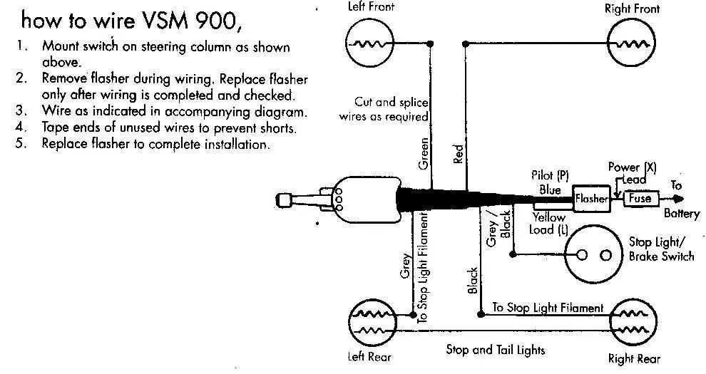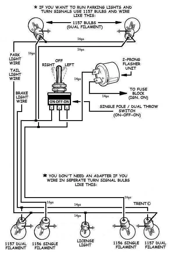
Ensure proper installation of the electrical components responsible for indicating direction changes on your vehicle. This involves accurate connection of the control unit, which manages the left and right signal actions, to the appropriate power source and control systems. The key to a reliable setup is understanding the positioning and interaction of each wire, as well as the correct mapping to the corresponding circuits.
First step: Identify the power input, typically connected to the vehicle’s main power system. Then, ensure the output is properly linked to the signal lights on both the front and rear of the vehicle. Verify that all connectors are firmly secured and properly insulated to prevent any short circuits.
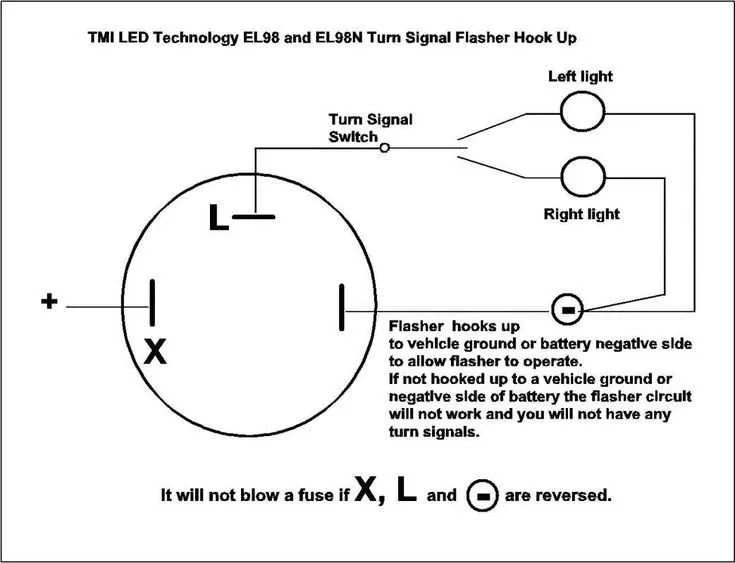
Next, focus on grounding. A consistent, low-resistance path is crucial to ensure the indicators function correctly. If necessary, use a multimeter to check the continuity of the grounding path. Also, be aware of any additional systems integrated with the indicator mechanism, such as emergency lights or warning signals, which may require their own wiring considerations.
Electrical Connection Guide for Vehicle Direction Indicators
Start by identifying the terminal numbers on the control assembly. Typically, terminals are marked as 1, 2, 3, and 4, where each connects to specific components. The first terminal often links to the left side of the vehicle, while the second terminal connects to the right side. The third terminal is usually designated for the main power input, while the fourth terminal goes to the grounding point.
To ensure proper functionality, connect the left and right terminals to the respective front and rear indicator lights. The power input terminal should be linked to the vehicle’s electrical system to receive current when activated. For a functional ground, ensure the fourth terminal is securely attached to a metal part of the vehicle’s frame.
It is essential to use appropriate gauge wires for each connection, with heavier gauge for power lines and thinner wires for ground and signal lines. Double-check that the ground is free from paint or corrosion to maintain a solid connection.
Test the system by applying power and activating the control mechanism. Verify that each light responds correctly to the input signals, and check for any flickering or malfunction. If issues arise, revisit the connection points and check for loose or improperly wired terminals.
Identifying Wires in a Multi-Function Control Device
Begin by locating the main connector that links the control mechanism to the electrical system. Typically, this connector features multiple colored wires, each representing a specific function. To ensure proper connections, refer to the color codes, which are commonly standardized. For example, the wire for the left indicator is usually green or white, while the right one may be yellow or blue.
Power Supply: Identify the wire carrying power from the battery or fuse box. This wire is often red or black and should be checked for continuity with a multimeter.
Activation: The wire that activates the mechanism is often marked with a different color, such as black or brown. This should be connected to the power input of the vehicle’s control unit.
Indicator Function: Look for wires connected to the indicator bulbs. These are typically green for the left side and yellow for the right. These wires must be traced back to the vehicle’s light bulbs to ensure correct connection.
Grounding Wires: A ground wire is essential for completing the circuit. Usually, it is a black or brown wire, attached to the vehicle’s metal frame. Test for a proper connection by ensuring it leads to a metal point with no insulation.
After confirming all wire connections, double-check for any frays or exposed sections that could lead to short circuits. Proper insulation and secure connections are crucial for the safe operation of the device.
Step-by-Step Guide to Connecting the Direction Indicator Lever

Begin by identifying the proper terminals on the lever and ensuring you have the correct wiring tools. Follow these steps to ensure accurate installation:
- Step 1: Disconnect the battery to prevent any electrical mishaps during the installation process.
- Step 2: Remove the cover or housing around the lever. This will give you direct access to the internal components.
- Step 3: Locate the wire connection points. Typically, these will be color-coded for easy identification.
- Step 4: Strip the ends of the wires to expose the bare copper. Use a wire stripper to ensure a clean and safe connection.
- Step 5: Attach the corresponding wires to the correct terminals. Refer to the color-coding or the manual for precise connections.
- Step 6: Secure the wire connections using wire nuts or terminal connectors, ensuring a tight fit to avoid loose connections.
- Step 7: After securing all connections, check for any exposed wires that could cause a short. Insulate them with electrical tape or shrink tubing.
- Step 8: Test the system by reconnecting the battery and verifying the functionality of the lever. Make sure the indicators activate correctly when the lever is moved.
- Step 9: If everything is working properly, reassemble the housing and ensure the lever moves smoothly without obstruction.
By following these steps precisely, you can achieve a safe and effective installation of your directional indicator lever.
Common Issues and Troubleshooting in Signal Control Mechanism

Check the fuse first if the lights aren’t functioning properly. A blown fuse is often the primary cause of malfunction in these electrical components. If the fuse is intact, proceed by inspecting the connection points to ensure no loose or corroded terminals are present. Corrosion is common in outdoor environments and can disrupt the flow of electricity.
If the indicators are blinking too rapidly or not blinking at all, a common issue could be a faulty relay. Replace the relay if the clicking sound is absent when engaging the mechanism, indicating it’s not operating as it should. Additionally, faulty relays may cause intermittent operation, where the lights flicker or fail after a few uses.
Another frequent problem arises from wear and tear of the stalk mechanism itself. Over time, internal contacts within the stalk can degrade, causing inconsistent functioning. If rotating the stalk doesn’t consistently engage the lights, the stalk may need to be replaced or cleaned. This issue is more prominent in older vehicles.
Wiring faults, such as short circuits or broken wires, are another reason for malfunction. Inspect the wiring harness thoroughly for any signs of fraying or exposed wires. If the connection seems loose or disconnected, reattach or replace the damaged components to restore normal operation.
In some cases, a malfunctioning relay or stalk could result in the lights flashing incorrectly. This is often due to electrical interference or faulty ground connections. Check the grounding of the system and ensure all components are properly earthed to eliminate this issue.