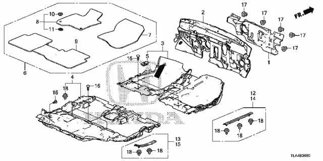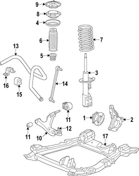
Start by inspecting the lower chassis area near the front axle. The front subframe supports the engine cradle and is connected to control arms, sway bar links, and the steering rack. Look for signs of corrosion around the mounting points, especially where the frame meets the suspension brackets.
The exhaust routing runs from the manifold underneath the passenger side, curving around the heat shields before reaching the resonator and rear muffler. Check for secure hangers and rusted flanges. Heat shields should be tightly fastened to avoid rattling or heat damage to adjacent parts.
Fuel system lines are mounted along the passenger side rail, protected by plastic covers. These covers can trap moisture, so it’s essential to remove and inspect beneath them annually. Ensure that rubber hose connections at the filter and tank junctions show no signs of cracking.
Rear components include an independent multi-link setup with trailing arms and lateral links anchored to the unibody frame. The differential (on AWD versions) is bolted to a crossmember near the rear axle. Pay attention to the CV axle boots and the condition of the bushings, which often degrade after 80,000 miles.
Braking hardware is distributed along both axles with hard lines running through the center tunnel. Rubber hoses at each wheel should be checked for bulges or leaks. ABS wiring is typically routed along the same path, clipped into molded brackets on the subfloor structure.
CR-V Chassis Layout Reference
Start by examining the lower frame structure near the front crossmember. You’ll locate the front subframe, typically bolted with six main fasteners, supporting the steering rack and control arms. Inspect for signs of rust along weld seams and mounting points, especially where the sway bar links attach.
Move to the midsection where the exhaust piping runs parallel to the driveshaft on AWD models. Heat shields are attached via small bolts–check for loose fittings or corrosion-induced vibration sources. Fuel and brake lines run along the right-hand side, clipped into place on the inner rocker panel flange.
At the rear, observe the multi-link suspension setup. Each trailing arm connects to the main rear crossbeam with heavy-duty bushings. Check for worn rubber in the upper arm links and inspect the coil spring seat for debris accumulation or paint flaking, both early signs of wear or impact damage.
Identifying Suspension Components in the CR-V Undercarriage
Start by locating the front control arms–triangular metal structures connecting the frame to the wheel hub. These parts allow vertical movement while maintaining lateral stability. Inspect the rubber bushings at the chassis mounting points for signs of wear or cracking.
Next, examine the strut assemblies behind the wheels. Each unit integrates a coil spring and a shock absorber. The top mounts are secured to the body with three bolts; check for fluid leakage or corrosion around the strut tube and mounting area.
Move toward the rear axle area and identify the trailing arms–longer rods aligned parallel to the frame. These are attached to the subframe with heavy-duty bushings. Inspect for rust, deformation, or any lateral play when pressure is applied.
Look for stabilizer bars at both ends. These horizontal rods connect the left and right sides through drop links. Examine the joints and bushings for looseness or torn rubber. Excessive sway during cornering often points to worn stabilizer links.
Finally, locate the toe and camber adjustment arms on the rear. These thinner components have eccentric bolts for alignment correction. Surface rust is common but shouldn’t affect integrity unless severe. Tighten bolts to specification after inspection.
Locating Drain Points and Skid Plates on the Underside
Start by positioning the vehicle on a flat, secure surface and engage wheel chocks for stability. Use a floor jack and jack stands to lift and support the front end if necessary.
Oil drain plug is located near the rear of the engine cradle, typically on the lower part of the oil pan. It’s a 17mm hex bolt, easily accessible without removing any covers. Place a drain pan beneath it before loosening to prevent spills.
Transmission fluid drain bolt can be found slightly rearward of the oil pan, usually on the driver’s side. It’s recessed and may require a 3/8-inch square drive tool.
Engine coolant drain cock is positioned at the bottom of the radiator, facing the front. Twist counterclockwise to open. A secondary block drain bolt may be mounted on the rear engine block wall for full system drainage.
Skid shields are mounted with 10mm and 12mm bolts and plastic push clips. Begin removal at the front edge near the bumper, then detach rearward. Skid panels typically protect the oil pan, transmission housing, and exhaust Y-pipe junctions.
Access hatches within the panels often allow service without full removal. Locate these rectangular or circular ports directly beneath the oil filter and drain plug area. They are secured with twist-locks or removable clips.
Inspect aluminum or steel plate mounts for signs of rust around fasteners. Use penetrating oil if bolts are seized. Torque fasteners to factory spec during reinstallation to avoid thread damage or loss under vibration.
Understanding the Layout of Fuel and Brake Lines

Inspect the routing of both systems by starting at the engine bay and tracing them along the vehicle’s frame rails. Brake lines usually run along the driver’s side, while fuel lines are commonly positioned on the opposite side.
- Brake Lines: Typically rigid steel tubing, secured with clips to the body or subframe. Look for rubber flex sections near wheel hubs.
- Fuel Lines: Often made of plastic or metal with quick-connect fittings. Positioned away from heat sources and protected by shields or channels.
To identify potential issues, check for:
- Corrosion: Most common near mounting clips or where road debris accumulates.
- Abrasion: Lines rubbing against metal parts or suspension components indicate improper mounting.
- Leaks: Wet spots or strong fuel odor can pinpoint deteriorated sections or faulty joints.
Ensure that replacement lines follow factory routing. Deviations can interfere with suspension travel or expose lines to exhaust heat. Always use OEM-style brackets and insulators to prevent vibration damage.