For efficient troubleshooting and repair of your Volkswagen’s electrical system, knowing the exact arrangement of its power distribution is crucial. Understanding where each connection is located ensures you can quickly address any malfunctions. It’s recommended to refer to the vehicle’s manual for precise locations, but if that’s not available, this guide will help you identify the main clusters of electrical connections in your VW model.
Each section of the vehicle’s wiring system serves a specific function. The main compartment typically houses the critical circuits for the engine and cabin controls. Ensure you always check the relays and their positioning when working on specific components. Proper identification reduces the risk of errors during repairs.
Always disconnect the vehicle’s battery before handling any electrical components. This prevents short circuits and ensures your safety while working with the system. Pay attention to the manufacturer’s specifications for each model, as some variations exist between different VW models, including the types of connections used and the placement of the components.
By understanding how power is routed throughout the vehicle, you’ll have a clearer picture when diagnosing issues, whether it’s a malfunctioning light, power windows, or ignition problems. Make sure to check for any signs of wear, as faulty wiring or corroded terminals can lead to system failure.
VW Electrical Circuit Layout Overview
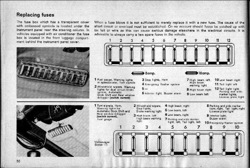
To ensure proper functionality of your VW vehicle’s electrical system, refer to the detailed schematic for the location and purpose of each protective component. For most models, the primary control units are located under the dashboard and near the engine bay, designed to safeguard critical systems such as lighting, power windows, and the central locking mechanism. Understanding the arrangement of these elements can prevent unnecessary repairs and electrical malfunctions.
Engine Compartment Configuration: Typically, the engine area houses the more powerful connectors for major systems like the alternator and air conditioning. These should be checked regularly for signs of wear or corrosion. Ensure the connectors are tightly secured and the corresponding wires are intact.
Interior Panel Details: In the cabin, you’ll find a secondary arrangement that manages systems like the radio, HVAC controls, and interior lighting. If any of these components stop working, it’s usually due to a disrupted connection in this section. Double-check the positioning and condition of the connectors, and replace any that seem damaged.
Access and Replacement: Always turn off the ignition and disconnect the car’s battery before accessing any electrical parts. Use a multimeter to verify the functionality of the protective elements before replacing them to avoid potential damage to the electrical components.
Ensure to follow the specific model’s manual to confirm the precise locations, as these can vary depending on the year and variant of your VW. Regular checks and replacements will ensure optimal vehicle performance and prevent unnecessary electrical failures.
Identifying Components in VW Electrical Panel
To identify the correct components in the VW electrical panel, follow these steps:
- Locate the reference guide for the specific model year.
- Examine the labels next to each slot for identification numbers.
- Match the numbers to the functions listed in your vehicle’s manual.
- Check the amperage ratings printed beside each circuit for additional clarity.
- If the slots are unclear, use a multimeter to test continuity to ensure proper identification.
Always consult your vehicle’s manual for exact configurations, as placement may vary across different models.
Common Locations for Electrical Circuit Protection
The most frequent positions for circuit protection components in Volkswagen vehicles include the dashboard panel, engine compartment, and sometimes near the footwell or side panels. Key systems such as lighting, air conditioning, and the central locking mechanism often have their protectors located in the cabin’s primary compartment. The most easily accessible are usually under the steering wheel, in the vicinity of the driver’s side door, or on the passenger side.
Interior: Look for protective components beneath the steering wheel or near the glove compartment. The rear and front windows, along with the entertainment system, typically feature these components in these regions. These are often housed within a protective cover that’s simple to remove by hand or with basic tools.
Engine Area: In the engine compartment, check the area near the battery or along the edges of the engine bay. These are usually enclosed within a weather-resistant casing to ensure they stay safe from engine heat and weather conditions. Some models also have protective components near the windshield or along the frame, shielded by a plastic cover.
Special Considerations: For some Volkswagen models, there are additional locations, such as the footwell under the dash or alongside the wheel wells. These tend to be harder to reach, requiring either the removal of panels or special tools to access them.
Ensure proper inspection of each area to avoid electrical faults in crucial systems, ensuring safety and functionality.
Steps for Replacing a Blown Fuse in VW
1. Locate the electrical component malfunctioning and identify the corresponding circuit in the vehicle’s manual. This will help you pinpoint the specific area to check for the faulty link.
2. Turn off the engine and all electrical devices. For added safety, disconnect the vehicle’s battery to avoid accidental short-circuiting during the repair process.
3. Access the panel where the damaged component resides, typically found under the dashboard or near the engine compartment. Open it carefully, ensuring you have full visibility of the connections.
4. Check the visible condition of the malfunctioning part. A burnt or broken conductor typically indicates the need for replacement.
5. Use appropriate tools to remove the defective element, ensuring you do not damage the surrounding connections or wires.
6. Replace with a new part that matches the voltage and current ratings of the original. Verify that the replacement part fits snugly into its housing.
7. After installation, reconnect the battery and test the electrical system to confirm proper function of the replaced element.