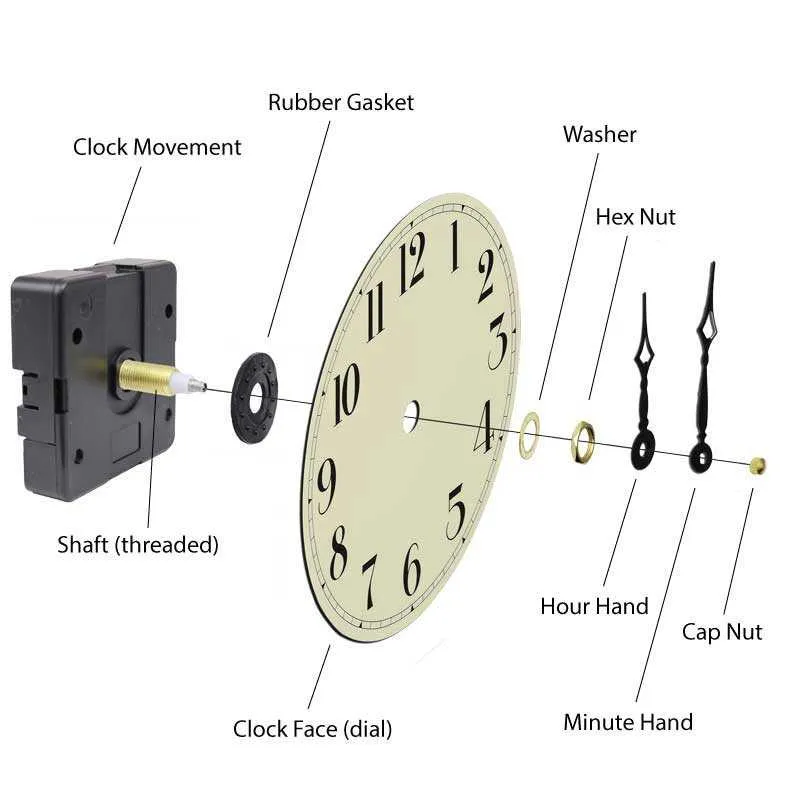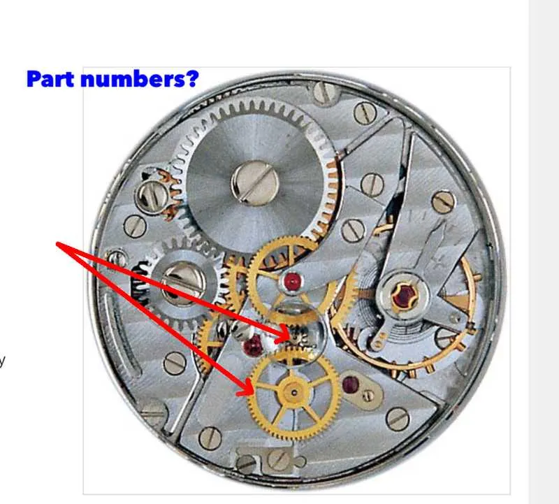
Begin by isolating each segment of the graphic to ensure focused attention on individual components without distraction. Breaking down a complex illustration into manageable sections allows for precise understanding of functional relationships and underlying data.
Prioritize clarity by examining one element at a time, verifying how it connects to adjacent structures. This approach minimizes cognitive overload and highlights critical interactions within the schematic.
Use a systematic method to navigate through the layers, starting from foundational elements and advancing toward intricate details. Document insights at each stage to track progress and avoid overlooking subtle yet significant features.
Employ magnification tools or digital zoom to enhance visibility of fine lines or annotations, ensuring no detail is missed during examination. This technique is particularly useful when dealing with dense or highly technical illustrations.
Identifying Main Components in a Timepiece Blueprint

Focus first on locating the movement mechanism, typically positioned centrally; it includes gears, escapement, and mainspring. Recognize the gear train by its series of interlocking wheels transferring energy from the power source to the regulating system. Spot the balance wheel and hairspring assembly, which control oscillation frequency and ensure precision.
Locate the power reservoir, often illustrated as a coiled spring or barrel housing the mainspring. Identify the escapement unit by its pallet fork and escape wheel, responsible for regulating energy release. The dial and hands assembly should be marked clearly as the interface displaying time information.
Note the casing outline, which protects internal components and influences structural integrity. Pay attention to winding and setting mechanisms, usually represented by crown stems and related levers. Understanding the layout of these fundamental elements enables efficient interpretation of the technical illustration.
Interpreting Mechanical Movement in Timepiece Schematics

Focus first on identifying the gear train layout: observe the sequence of wheels and pinions transferring energy from the mainspring barrel to the escapement. Note the number of teeth on each cogwheel to understand the gear ratio and resulting speed reductions.
Next, analyze the escapement mechanism–look for the pallet fork and escape wheel interaction. Verify the lever angles and impulse directions to determine how energy is regulated for accurate oscillations of the balance wheel.
Examine the balance assembly: check the hairspring’s position and attachment points, as well as the balance staff pivots. Precise alignment here is critical for maintaining consistent timing intervals.
Inspect the mainspring barrel’s integration with the winding system by tracing the ratchet wheel and click. Confirm how the winding mechanism engages and prevents unwinding.
Lastly, interpret the keyless works by following the motion transmitted through setting levers and sliding pinions, ensuring correct engagement for time adjustment without disrupting power flow.
Understanding Gear Train Layout and Function

Position each gear to maintain precise engagement: the center distance must match the sum of their pitch radii to avoid slippage or excessive wear. Employ a combination of spur and pinion gears arranged in a series to achieve accurate speed reduction or amplification. The gear ratio is calculated by dividing the number of teeth on the driven gear by the number on the driver gear; use this ratio to control rotational speed and torque transmission effectively.
Ensure that the axes of the gears remain parallel in a standard layout, preventing misalignment that causes inefficiency and noise. Utilize intermediate wheels to transmit motion over longer distances while preserving the angular velocity ratio. The material and tooth profile, typically involute, influence durability and smoothness of engagement; prioritize hardened steel for longevity in high-stress points.
Integrate idler gears only to change rotation direction without altering the gear ratio. Maintain minimal backlash–ideally between 0.05 and 0.15 degrees–to balance smooth operation and reduce mechanical stress. Lubricate contact surfaces adequately to lower friction and extend lifespan. Apply these principles for a compact, efficient transmission system that delivers consistent, accurate movement control.