To ensure reliable operation of your garden vehicle, start by identifying the main power sources and grounding points. A consistent 12-volt supply should be confirmed at the battery terminals, with careful attention to polarity and cable integrity.
Key components such as the ignition switch, safety interlocks, and starter solenoid must be linked precisely according to their function. Misrouting or loose contacts can lead to intermittent failures or total system shutdown.
Fuse protection is critical; verify the correct rating is installed to prevent damage to sensitive electronics and wiring harnesses. Additionally, all connectors should be clean and secure, minimizing resistance and heat buildup during operation.
Mapping each circuit path with clear labeling helps diagnose issues quickly and reduces the risk of electrical faults. Use color-coded wires and refer to manufacturer specifications to match each line with its corresponding role.
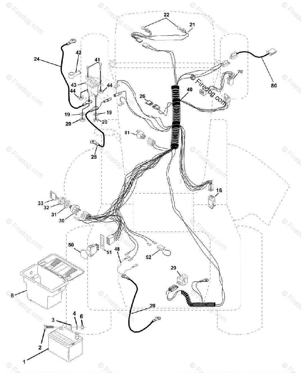
Electrical Schematic of a Craftsman Lawn Tractor
Ensure all power connections are secure and corrosion-free to maintain reliable operation. The ignition switch typically controls the main circuit, connecting the battery to the starter solenoid and safety interlocks.
Follow color-coded lines carefully: red wires usually indicate positive battery feeds, black or brown represent ground paths, and yellow or blue are for control signals such as PTO engagement or brake switches.
Check the fuse rating on the main power line–commonly a 20-amp fuse–to protect circuits from overload. The solenoid receives a direct feed from the battery and activates the starter motor when the ignition is engaged.
Safety interlocks, including the seat switch and brake sensor, must be wired in series to the ignition circuit to prevent engine start under unsafe conditions. The headlight circuits often run through a separate relay controlled by the main switch.
Refer to connector pin assignments: the battery positive terminal connects to the starter relay and fuse block; the ignition terminal powers the coil and control switches. Ensure the alternator output is routed back to the battery to maintain charge.
Identifying Key Electrical Components and Their Connections

Start by locating the battery terminals and verifying proper polarity to prevent damage. Follow the main power cables to the ignition switch, ensuring secure connections and corrosion-free contacts.
- Battery: Provides 12V DC power; terminals must be clean and tight.
- Ignition Switch: Controls engine start; wires typically color-coded (red for power in, yellow for ignition out).
- Fuse Box: Protects circuits; check fuses for continuity and correct amperage ratings.
- Starter Solenoid: Acts as relay; large gauge cables from battery and starter motor, smaller trigger wire from ignition switch.
- Blade Engagement Switch: Safety interlock; wires often green and black, verify continuity when activated.
- Safety Interlock System: Includes seat switch and brake switch; usually connected in series to prevent engine start if conditions aren’t met.
- Charging System: Alternator or stator wiring connected to battery and regulator; inspect for worn insulation and secure mounting.
Trace each harness segment methodically using a multimeter to confirm voltage presence and ground continuity. Replace any frayed or brittle wires immediately to avoid shorts.
- Disconnect the negative battery terminal before testing or servicing.
- Identify wire colors against the schematic to avoid misconnection.
- Use connectors rated for the expected current load.
- Secure all terminals with dielectric grease to reduce oxidation.
- Ensure routing avoids sharp edges and moving parts.
Adhering to these precise steps will maintain reliable electrical performance and extend component lifespan.
Step-by-Step Guide to Tracing and Repairing Electrical Faults
Begin by disconnecting the power source to prevent shorts or shocks. Use a multimeter set to continuity mode to check each conductor path individually. Identify breaks by probing both ends of a suspected line and confirming lack of connection.
Follow the harness from the battery terminal through each connector and junction. Inspect connectors for corrosion or loose contacts, as these often cause intermittent failures. Clean or replace affected plugs to restore proper flow.
Pinpoint damaged insulation by visual inspection under bright light; exposed wires risk short circuits. Use electrical tape or heat-shrink tubing to reinforce protection after repairing breaks with solder or crimp connectors.
Test each switch and relay in sequence by measuring voltage across terminals while activating controls. Faulty components will show no voltage change or inconsistent readings, signaling replacement necessity.
For motor or solenoid issues, measure resistance values against manufacturer specs to detect coil damage or open circuits. Replace any element showing infinite resistance or significant deviation.
After repairs, restore power and verify system functionality by cycling all controls. Confirm stable voltage at key points to ensure restored integrity and eliminate intermittent faults before full operation.
Replacing and Upgrading Harnesses Safely
Always disconnect the power source before starting any electrical overhaul. Use insulated tools and verify zero voltage with a multimeter to prevent shocks or short circuits.
Choose harnesses that match or exceed the original gauge and insulation standards. Thicker wires reduce resistance and improve durability under load. Avoid cheap substitutes that risk overheating.
Label all connectors during disassembly to ensure accurate reconnection. Take photos or mark terminal positions to maintain proper circuitry alignment.
Secure cables using clamps or zip ties to prevent abrasion and vibration damage. Routing should avoid sharp edges, moving parts, and excessive heat sources.
When upgrading, consider weather-resistant components with UV-stable sheathing if exposed to sunlight or moisture. This extends longevity and reduces corrosion risk.
Test continuity and function of each circuit after installation before full operation. Address any irregularities immediately to prevent electrical faults or equipment failure.