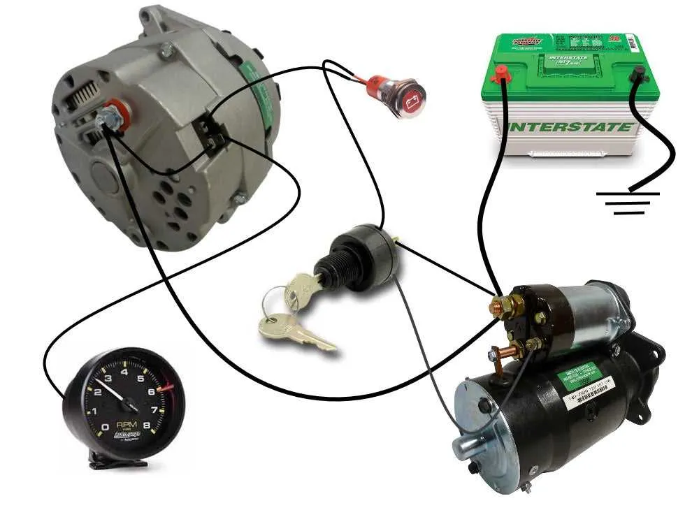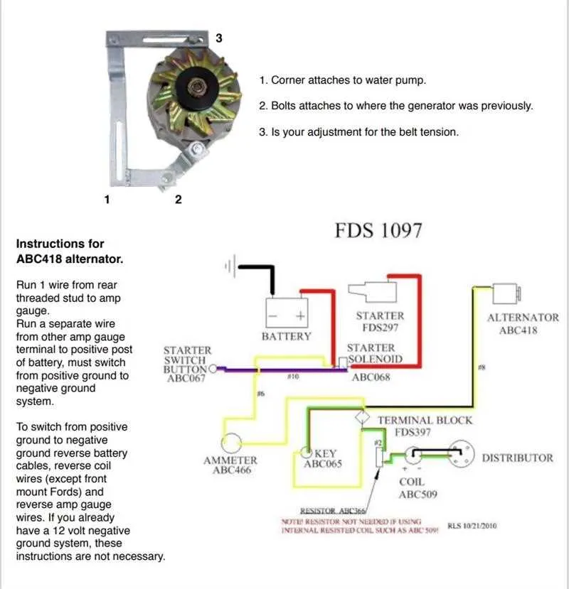
To simplify the charging process, connect the system with a single lead for monitoring voltage. Use a voltage sensing unit to regulate the charging voltage and prevent overcharging, ensuring efficiency in the electrical flow. Connect the sensor to the output terminal for accurate readings of the battery’s charge level.
Ensure the ground wire is attached securely to the vehicle’s chassis or frame. This helps maintain a steady current flow and minimizes the risk of electrical interference or short circuits. Proper grounding will stabilize voltage levels and prevent fluctuations that could damage components.
For added protection, consider incorporating a voltage regulator into the circuit. It automatically adjusts the voltage to the optimal level, avoiding undercharging or excessive energy input. Be mindful of using high-quality connectors to avoid potential corrosion or wear over time.
Make sure the system is compatible with the power requirements of the device being charged. Conduct regular checks to ensure the setup is working properly and providing consistent energy output without overheating or excessive power loss.
1 Wire Charging System Setup
To set up a 1-wire charging system, follow these precise steps to ensure efficient electrical flow. The process simplifies the installation by using only a single connection for both the power output and control functions.
- Connect the primary terminal to the positive side of the battery. This will serve as the source for the energy supply.
- Ensure the ground is securely attached to a solid frame or chassis to complete the circuit.
- Install the regulator in such a way that it receives direct power from the charging unit, eliminating the need for additional control terminals.
- The energizing circuit will operate autonomously once connected, as the system is designed for self-excitation, removing the need for separate excitation feeds.
- Confirm that the charging unit is compatible with your specific setup. Not all systems are designed to function with a single lead; compatibility is key for optimal performance.
By implementing this method, the setup becomes less complicated, reducing the amount of components necessary for a fully operational energy source. Make sure to test the entire system for proper output and functionality once installed.
Wiring a 1 Wire Charging System for Automotive Applications
For a simple and efficient charging setup in vehicles, using a 1-wire configuration is highly effective. It reduces complexity by connecting the charging system to a single lead. Below are the steps for installing this system, along with crucial considerations for proper setup.
| Component | Connection Type | Recommendation |
|---|---|---|
| Charging Unit | Single Lead | Ensure a solid, corrosion-free connection directly to the battery’s positive terminal. |
| Grounding | Chassis Ground | Ground the unit to the vehicle’s chassis to prevent electrical interference. |
| Field Connection | Internal Regulation | Internal regulation allows automatic control of output voltage; no separate field connection needed. |
| Indicator Lead | Optional | If required, install a low-current signal wire to indicate charging status. |
For optimal performance, choose a unit designed for automotive use with an internal regulator that adjusts output to suit the vehicle’s electrical needs. Always use cables with adequate insulation and gauge to handle the current without overheating.
When connecting to the battery, ensure the positive terminal is connected securely. In vehicles with advanced electrical systems, you may also want to install a fuse or breaker to protect the circuit. Ensure the grounding connection is clean and reliable, as poor grounding can lead to inefficient charging.
Once the setup is complete, test the system by monitoring the battery voltage while the engine is running. It should show a slight increase when the charging unit is operational. If the voltage remains constant or drops, check the connections for looseness or corrosion.
How to Identify Key Components in a 1 Wire Alternator Circuit
Start by locating the main terminal, which connects to the battery or electrical system. This component is essential for supplying power. It’s typically the largest connector and often has a heavy gauge lead attached.
Next, find the exciter terminal, which is used for providing a small voltage to the regulator. In a 1-wire setup, this terminal is usually absent or internally connected, simplifying the circuit. If visible, it will be a smaller connector.
The voltage regulator plays a critical role in controlling output. In a simplified design, this may be part of the unit itself and not externally mounted. It’s responsible for maintaining the correct charge voltage.
Lastly, check for the ground connection, ensuring it’s properly bonded to the vehicle frame or engine. Poor grounding can lead to voltage fluctuations or system failure.
Troubleshooting Common Issues in 1 Wire Alternator Connections

Ensure the main connection to the battery is secure. A loose or corroded terminal can prevent proper charging, causing voltage fluctuations or failure to charge the battery. Check for any signs of wear or damage around the connection points.
If the charging voltage is low, inspect the signal from the charging terminal. A weak signal could mean poor grounding or a faulty connection, which can affect performance. Verify the integrity of the ground path and the stability of the terminal connections.
If the system is not generating any output, test the voltage at the regulator terminal. No voltage reading could indicate a broken regulator, while an overcharged reading suggests it might be stuck in the “on” state. Either situation requires immediate inspection and possible replacement.
Inconsistent charging behavior could also be related to the resistance within the system. Excessive resistance can interfere with proper function, so it’s important to check all connectors and cables for high resistance points, replacing any corroded or damaged parts.
If the charging system fails to activate upon starting the engine, check the activation terminal for continuity. A lack of continuity can prevent the system from detecting the engine start signal, leading to charging failure.
For systems that are charging intermittently, confirm the voltage output during both idle and higher RPM conditions. A fluctuating output is often caused by an unstable connection or voltage regulator. Tightening loose connectors can often resolve this issue.