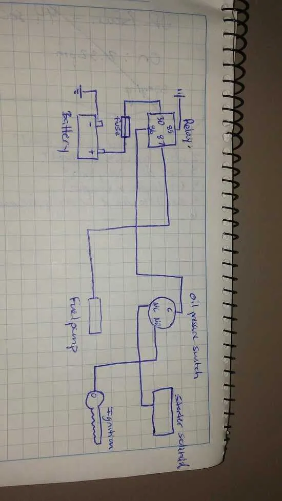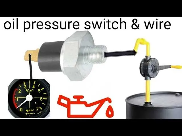
Ensure the sensor terminal is securely attached to the control circuit using a compatible connector designed for one conductor. Proper insulation and a firm mechanical connection prevent signal loss and false readings.
Grounding the sensor body to the chassis or engine block is essential for accurate functionality. Confirm continuity between the sensor casing and the negative terminal of the power source to avoid erratic indicator behavior.
Integrate the sensor output directly into the dashboard alert system by linking the single conductor to the input terminal of the warning light module. Use a fuse inline to protect the circuit from short circuits or voltage spikes.
1 Wire Oil Pressure Switch Wiring Diagram
Connect the single conductor from the sensor directly to the warning light circuit or gauge input. The sensor body must be grounded to the engine block or chassis to complete the electrical path. Ensure the connection is secure and free of corrosion to maintain accurate signal transmission.
Use a high-temperature resistant conductor rated for automotive environments, preferably with insulation that can withstand engine heat and oil exposure. Route the lead away from moving parts and extreme heat sources to prevent damage or signal interference.
For vehicles with a warning lamp, connect the signal wire to the positive terminal of the indicator, with the other side of the lamp grounded. The sensor will close the circuit upon low fluid force, illuminating the light immediately.
When integrating with a gauge, verify the sensor’s compatibility with the instrument’s input range. Some units require a specific voltage or resistance to provide an accurate reading; adjust the sensor or gauge accordingly.
Test the system by applying mechanical pressure to the sensor and confirming the indicator responds properly. Replace or reseal the sensor if erratic or no response occurs, as a reliable connection is critical for safety monitoring.
How to Identify the Single Connection on a 1-Wire Sensor

Locate the terminal on the sensor that protrudes as a single post or stud, typically threaded for mounting. This contact serves as the sole electrical interface for the device.
Check for an insulated housing surrounding the base, ensuring only one metal point is exposed for attachment. The exposed point is designed to connect directly to the signaling conductor.
Confirm the connection type by verifying the absence of multiple terminals or plugs; the single contact is usually centered and isolated from the sensor body, which acts as the ground.
Use a multimeter to test continuity between the exposed terminal and the metal casing; a reading of no continuity confirms the single conductor point is separate and intended for signal transmission.
When installing, ensure the fastening nut or clip makes secure contact with this terminal, as it carries the feedback signal directly to the monitoring system.
Step-by-Step Guide to Connecting a 1 Wire Sensor

Begin by identifying the single conductor terminal on the device. Ensure the engine is off and the battery is disconnected to prevent short circuits.
Attach a suitable gauge conductor directly from the terminal to the indicator light or monitoring system input. Use a reliable connector to secure the connection and prevent corrosion.
Connect the ground lead from the engine block or chassis to the negative terminal of the monitoring system. This completes the electrical circuit necessary for accurate signal transmission.
Double-check all junctions for tightness and insulation to avoid false readings or signal loss. Use dielectric grease on terminals to enhance longevity and reduce oxidation.
After completing connections, reconnect the battery and start the engine. Observe the indicator to confirm the device activates at the correct threshold.
If the indicator remains off or shows irregular behavior, verify continuity with a multimeter and inspect for loose contacts or damaged conductors.
Troubleshooting Common Issues in 1 Wire Oil Pressure Switch Wiring
Begin by verifying the single conductor connection for continuity and secure attachment. Loose or corroded terminals cause intermittent faults.
- Use a multimeter to check resistance across the sensor terminal and ground. A reading outside manufacturer specifications indicates a defective unit.
- Inspect the connector for dirt, oxidation, or damaged pins that can disrupt signal transmission.
- Confirm proper grounding of the sender device; poor grounding often leads to false readings or no signal.
- Check for shorts by measuring continuity between the conductor and the chassis; continuity should be absent to prevent false alerts.
- Examine the harness length for damage or exposure to heat sources, which may degrade insulation and cause faults.
- Replace any brittle or cracked insulation immediately to avoid signal loss or short circuits.
- Ensure the gauge or monitoring unit receiving the signal is calibrated and functioning properly.
- Test the system under different engine conditions to identify intermittent failures linked to vibration or temperature.
Consistent application of these steps minimizes downtime and improves reliability in single conductor sensor circuits.