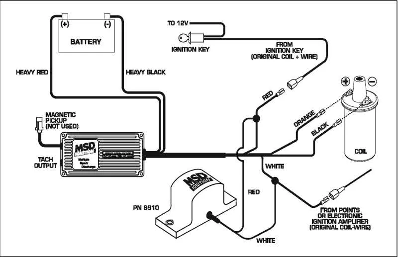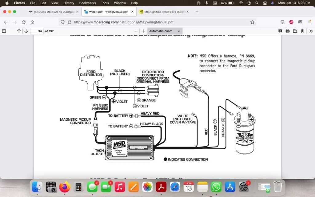
When setting up the ignition system for your engine, ensure proper connections for the 6A module to avoid misfiring and other performance issues. Begin by securely attaching the power and ground wires to ensure stable operation. A positive connection is required for consistent voltage delivery, while the negative should be firmly grounded to prevent electrical noise interference.
For the coil, make sure that the primary and secondary terminals are correctly configured. The primary side should be wired to the trigger signal, while the secondary leads go to the distributor or direct ignition components. Double-check each connection to prevent spark inconsistencies and potential damage to the components.
To optimize performance, it’s critical to adjust the signal-to-ignition ratio for accurate timing. Pay attention to the tachometer lead, which should be attached to the RPM input for accurate engine speed monitoring. Ensure that the trigger wires are placed precisely, as incorrect installation can lead to ignition failure or erratic engine behavior.
MSD 6A Connection Setup
To properly connect the MSD 6A ignition control module, start by ensuring that the power and ground wires are securely attached. The red wire should go to a 12V source, and the black wire must be connected to the chassis ground. This setup is critical for proper module operation.
Triggering the System: The green wire must be connected to the distributor or a tachometer signal for triggering. Make sure to securely fasten it to the signal output terminal.
Coil Integration: Connect the white wire to the negative side of the ignition coil. This connection will allow the unit to control spark timing. The coil should be a compatible 12V unit designed for high-performance ignition systems.
Important Note: If you’re integrating with a tachometer, use the violet wire to ensure proper signal transmission from the ignition system to the tach display. This wire must be routed to the tach’s input terminal, ensuring correct RPM reading.
Testing: Before final installation, it’s essential to test all connections using a multimeter. Ensure that each wire is receiving the correct voltage and signal. Double-check the power supply to the unit to avoid malfunctions.
Lastly, always consult the manufacturer’s specific documentation for any model-specific requirements or troubleshooting procedures. Proper installation is key for optimal performance and reliability.
How to Connect MSD 6A to the Ignition System
Start by disconnecting the battery to prevent any accidental short circuits. Then, locate the power input terminal on the ignition control module. Connect a 12-volt wire from the positive terminal of the battery to the “12V” input on the unit. Ensure the wire is fused for safety purposes. Next, find the tachometer lead from your ignition system and attach it to the designated tach input on the control unit.
The ignition coil connection is crucial. Take the wire from the negative terminal of the coil and connect it to the “coil negative” terminal of the module. For the coil positive connection, use the designated terminal on the ignition switch or main fuse box, depending on your setup.
Now, connect the ground terminal of the module directly to the vehicle’s chassis. Use a short, thick wire for a secure ground connection to avoid any interference or voltage drop.
Finally, verify all connections are solid, ensuring there are no loose wires or exposed terminals. Reconnect the battery and check for proper function before starting the engine.
Connecting the Ignition Control to a Tachometer and Rev Limiter

To set up the ignition module with a tachometer and rev limiter, follow these precise steps:
- Connect the tachometer signal: Locate the output terminal from the ignition unit, typically labeled “Tach” or “Tach Output”. This is where you will link the tachometer’s input wire.
- Rev limiter setup: The rev limiter input wire should be connected to the module’s “Rev Limiter” terminal. Ensure the rev limiter switch is properly configured to the desired RPM setting.
- Ground connections: Both the tachometer and rev limiter need a solid ground connection. Attach each of their ground wires to a common chassis ground or directly to the vehicle’s battery negative terminal.
- Power supply: The ignition system will require a dedicated 12V power source. Make sure this is routed from a clean, reliable power point in the vehicle’s electrical system.
- Signal integration: If using an aftermarket rev limiter, ensure the module’s input receives the correct signal voltage from the ignition unit. Verify the tachometer also receives an accurate signal for proper RPM display.
It’s crucial to double-check the wiring integrity before powering on the system to avoid any potential damage to connected components.
Troubleshooting Common Wiring Issues with MSD 6A
Check the ignition control box for proper grounding. A poor or inconsistent ground can lead to misfires or failure to start. Ensure that the ground wire is securely attached to a clean, bare metal surface on the vehicle’s frame or engine block.
If the system isn’t powering up, inspect the connection between the ignition control and the battery. Corroded or loose battery connections may cause intermittent power loss. Tighten and clean all connectors, ensuring no corrosion or wear on the leads.
Verify the trigger signal from the distributor. If the spark control unit doesn’t receive a clean signal, ignition timing issues may arise. Use a multimeter to check the voltage at the trigger wire while cranking the engine. A fluctuating signal could indicate a fault in the distributor or trigger mechanism.
Examine the output to the coil. A weak spark can result from a damaged or disconnected output lead. Inspect the coil for continuity and check the lead for any signs of wear or breakage. A faulty coil can significantly impact ignition performance.
If you experience backfires or irregular engine performance, inspect all connections for signs of shorts or crossed wires. Ensure that no wires are making contact with hot engine components or moving parts that could cause a short or wear through the insulation.
Test the system’s fuse and relay for continuity. A blown fuse or malfunctioning relay may disrupt the ignition system’s power supply. Replacing the fuse and relay with compatible parts should restore proper function.
When encountering a no-start condition, check the tachometer signal. A malfunctioning tach input may prevent the ignition system from functioning. Verify the signal from the tachometer and check for proper voltage or continuity to the control box.