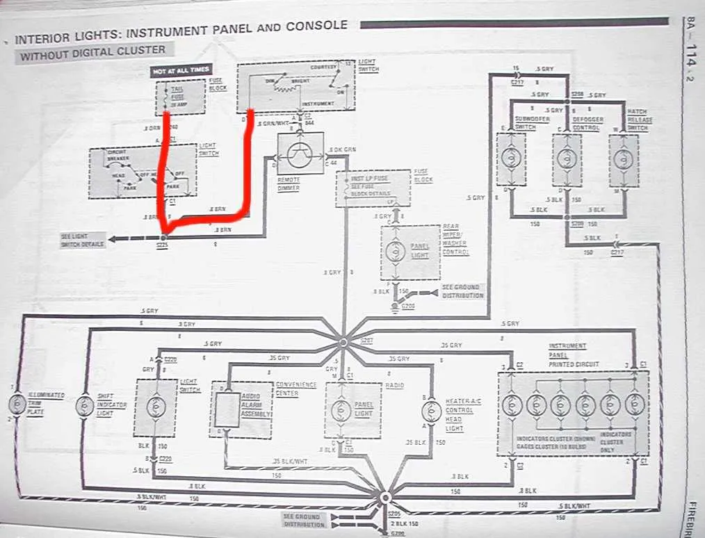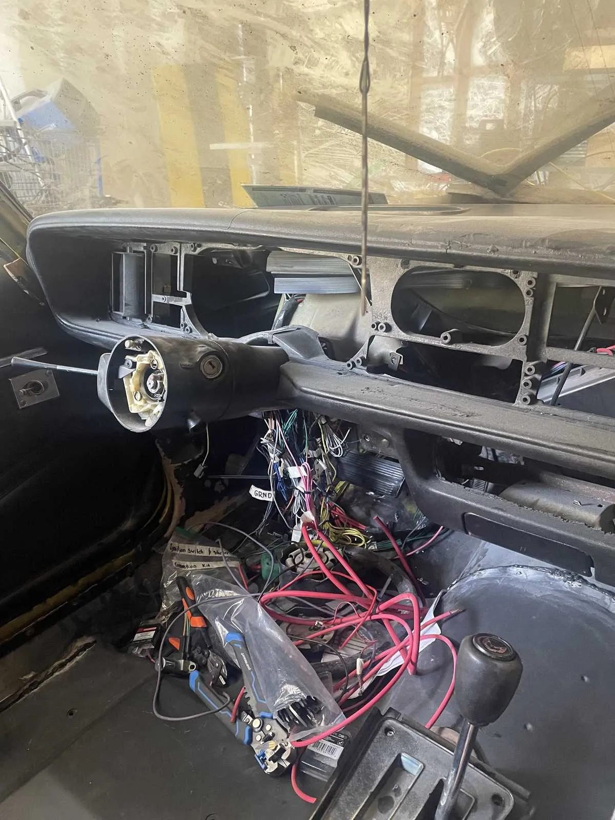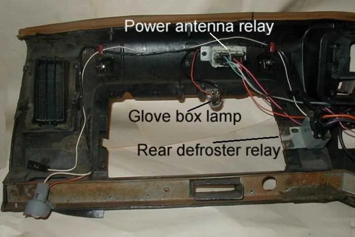
If you’re working on restoring or repairing the electrical system of a classic muscle car, you’ll need a detailed reference for the internal circuitry. Specifically, pay attention to the interconnections between the dashboard components and control systems. This includes switches, lights, gauges, and fuses–each essential for the car’s functionality and safety.
Understand the Component Connections: Each connection serves a purpose, from powering lights to controlling the engine management system. Begin by checking the routing of the wires that connect the dashboard to the central system. This will ensure a seamless flow of energy to each critical part.
Fuses and Circuit Protection: Identifying and securing the fuses is vital to prevent short circuits or damage. Always replace damaged fuses with exact equivalents to maintain the integrity of the circuit and avoid unnecessary breakdowns.
For those unfamiliar with the layout, it is essential to examine the pathway from the ignition system to each of the dashboard components. Clear labeling and a systematic approach to tracing the wires will save time and prevent costly mistakes during repairs.
Electrical Circuit Overview for the 1980 Muscle Car
When dealing with the electrical system of this iconic vehicle, focus on the main components that control the cabin functions, such as the gauges, switches, and lighting. Start by checking the connections at the central fuse block for continuity. Ensure that all the wires leading to the instrument cluster are secure and show no signs of corrosion or wear. This is critical to ensure proper voltage distribution to critical systems like the speedometer, tachometer, and warning lights.
Be aware of the color coding system for the connectors. The most common wires will include red for the power feed, black for ground, and green or yellow for specific signals to the gauge cluster. Pay close attention to the connection points near the steering column, where some wires split off to control smaller systems like the horn and turn signals.
If you encounter any electrical issues, use a multimeter to test for voltage at key points. Start with the ignition switch and trace power from there to the various control systems. Often, malfunctions are due to loose or faulty connections at the fuse panel or behind the dashboard components.
For accurate troubleshooting, refer to the vehicle’s factory manuals that provide detailed information on the pinouts and wire routing. Be mindful of the ground points throughout the car, especially those connected to the body, as a weak ground can lead to erratic readings or intermittent failures.
Lastly, consider using upgraded connectors and fuses if you’re restoring or replacing any components. This will help prevent future issues and maintain optimal performance of all electrical systems.
Understanding the Key Components of the Electrical Circuit for Interior Controls

Focus on the fuse box, which houses critical relays and fuses, protecting the system from short circuits. Regular inspection ensures proper functionality of the controls like lights, indicators, and gauges. Pay attention to the connections between the main harness and various switches. Faulty or corroded connectors can lead to intermittent issues with power delivery to essential components such as the speedometer or climate controls.
Another vital part is the ground system, which prevents electrical noise and reduces the risk of electrical malfunctions. Check grounding points for corrosion and ensure secure attachment to the vehicle’s frame. This step is especially important when troubleshooting problems with sensors or warning lights that might malfunction due to poor grounding.
When examining the control panel, ensure that the circuits for indicators, climate settings, and audio systems are well-integrated. They should be easily traceable through the harness for troubleshooting purposes. Keep an eye on the condition of the connectors–loose or oxidized terminals can lead to flickering or complete power loss to certain functions.
The control switches often feature integrated circuits that interact with various components, so regular checks for resistance values are necessary. If resistance readings are off, it could indicate a fault within the switch or a problem along the connecting lines.
Troubleshooting Electrical Issues in the Vehicle’s Control Panel

Start by checking the fuse box. A blown fuse can often be the cause of non-functioning components. Identify the relevant fuse for the faulty system and replace it if necessary. If the problem persists, move to the next step.
Inspect all connectors and terminals. Loose or corroded connections can lead to intermittent or complete loss of power. Disconnect the battery before cleaning any terminals. Use a wire brush to remove corrosion and secure any loose connections.
Test for continuity along the affected circuits using a multimeter. This will help identify any breaks or shorts in the system. Focus on areas where wires are exposed to movement or heat, such as near the dashboard or under the console.
If the previous steps don’t resolve the issue, check for faulty relays. A malfunctioning relay can prevent signals from reaching the proper components. Swap the relay with one from another circuit to test its functionality.
Finally, review the ground connections. A poor ground connection can result in erratic behavior in electrical systems. Ensure all ground points are clean, secure, and free from rust or dirt.
How to Properly Connect and Replace Wires in the Dashboard

Begin by disconnecting the battery to prevent any accidental short circuits while working on the electrical connections. Next, identify the damaged or old wires that need replacement or reconnection.
- Remove the panel or cover surrounding the instrument cluster carefully to access the wires behind it.
- Inspect each wire for any signs of wear or corrosion. If any wire is visibly damaged, use a wire stripper to remove the insulation from both ends of the wire.
- For new connections, use connectors that match the gauge of the wire. Always ensure a secure fit to avoid loose connections that could lead to electrical issues.
- Twist the new wire into place using the appropriate terminal connectors. Soldering the connection is an option, but make sure to use heat shrink tubing or electrical tape to cover the exposed section and ensure a safe connection.
- Reconnect any disconnected components, such as the light fixtures or gauges, ensuring the wire ends are properly aligned with the terminals.
After completing the wiring work, carefully test the system. Reconnect the battery and turn on the ignition to verify if all electrical components are functioning correctly. If anything is not working as expected, double-check the connections for loose or poorly attached wires.
- Make sure to follow proper wire routing to prevent any future interference with moving parts inside the vehicle.
- If using new wiring, choose high-quality, durable materials to avoid future problems.
When replacing or fixing electrical components, always prioritize safety. Wearing insulated gloves and using tools that are insulated can minimize the risk of electric shock or burns.