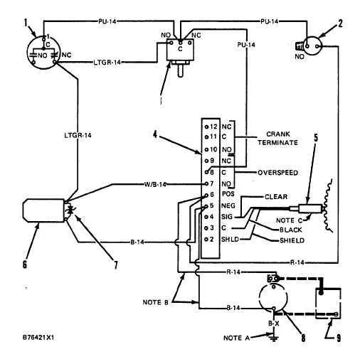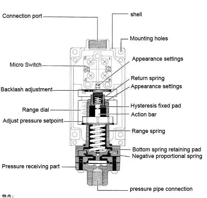
To ensure reliable operation of your water supply system, precise connections are crucial when setting up the pressure control unit. Begin by identifying the terminals designated for the input and output wires. The common terminal should connect to the power source, while the normally open (NO) and normally closed (NC) contacts will interface with the pump motor and control the on/off cycle based on system requirements.
Power source connection: Attach the incoming live wire to the common terminal, ensuring a solid connection. For safety, use proper insulation and verify that all wires are tightly secured to prevent loose connections.
Load connections: The NO terminal connects to the pump’s power input, which activates the pump when pressure drops below the preset value. The NC terminal can be used to control a secondary device or to activate an alarm if needed.
Grounding: Always ensure that the system is grounded appropriately to avoid electrical faults. Proper grounding provides safety and protects against damage to sensitive components.
Before powering on the system, double-check all connections for accuracy and stability. A malfunctioning link or improper setup could lead to the failure of the entire unit or even damage your equipment.
Connecting the Control Mechanism to the Pump System

Ensure proper connection of the control unit to the pump circuit to avoid electrical issues. Begin by connecting the power supply leads to the terminal block on the unit. The live (hot) wire should be routed to the designated input terminal, while the neutral wire connects to the neutral side. Next, link the pump’s power leads to the corresponding output terminals of the device. Typically, the terminal configuration will allow easy identification of the input and output connections for both live and neutral wiring.
Verify the grounding process by attaching the grounding wire to the dedicated terminal on the control component. This is crucial to prevent electrical surges or short circuits. After securing the electrical connections, confirm that all wiring is tight and no exposed wires are visible, as this could lead to potential hazards.
Test the system by powering up the unit and verifying that the circuit responds according to the required operational thresholds. If the system doesn’t function as expected, double-check the connections, ensuring that the right terminals are used and the wiring is secure.
Understanding the Basic Electrical Configuration of a Water Pump Regulator
Ensure correct power distribution by following these specific steps for connecting the pressure control device to the electrical system:
- Power Source: Connect the incoming live and neutral cables to the input terminals. The live wire should be linked to the terminal marked “L” or similar, while the neutral connects to the corresponding terminal.
- Control Terminal: The control terminal is responsible for managing the on/off functionality. This terminal will need to be wired to the activation point of your pump’s electrical setup.
- Grounding: Always ensure the unit is properly grounded to avoid electrical hazards. Attach the grounding wire to the designated ground terminal on the device.
- Additional Contacts: If your model features additional terminals (such as for a second contact), these can be linked to other equipment that responds to changes in system pressure.
- Voltage and Current Ratings: Double-check that the control system is rated to handle the voltage and current levels specific to your pump, avoiding overloads.
Following these configurations will help ensure reliable operation and safety of the system over time.
How to Properly Connect the Pressure Switch to a Pump and Power Source

Start by ensuring the power supply is disconnected to avoid any electrical hazards. Use a high-quality electrical cable rated for the required voltage and current. Connect the terminal on the device to the correct power input, making sure the polarity matches. If the system uses a 240V AC supply, double-check the wiring before completing the connection.
For the pump connection, ensure the two terminals are securely attached to the pump’s control relay. You must use the right gauge wire to handle the required amperage to avoid overheating and potential system failure. Tighten all terminals and double-check for proper grounding to prevent electrical shock or equipment damage.
Finally, use a reliable junction box to house all exposed connections, ensuring it is properly sealed to protect from moisture or dirt. Avoid using low-quality connectors, as this can cause corrosion over time and reduce system reliability.
Common Connection Issues and Troubleshooting Tips
Start by checking the power supply to ensure the device is receiving voltage within the specified range. A fluctuating or insufficient current can cause erratic behavior or failure to activate. Inspect the terminals for loose or corroded connections, as this may lead to intermittent functionality.
If the unit fails to respond, verify the continuity of the control circuit. Faulty relays or faulty sensors are often culprits, and replacing them may restore functionality. Pay attention to any worn-out seals or improper assembly, as leaks or blockages can prevent correct operation.
Ensure that the settings are correctly calibrated according to the specifications. Misalignment between the operational limits and the actual system parameters can result in non-engagement or over-triggering. Adjust the settings as needed to maintain consistent performance.
Be mindful of the environment where the system is installed. Extreme temperatures, humidity, or exposure to chemicals can deteriorate internal components. In such cases, consider installing protective covers or relocating the unit to a more controlled space.
If troubleshooting does not resolve the issue, consider performing a reset by disconnecting the unit for several minutes, then reconnecting. This may clear any internal errors that are preventing proper operation. If issues persist, consult a professional technician for further diagnosis.