If you’re troubleshooting electrical issues or upgrading the components of your pickup, understanding the relay and wiring system is crucial. The first step in diagnosing or replacing any electrical part is to familiarize yourself with the exact location and function of each relay and connection in the engine compartment.
Locate the central electrical panel situated near the engine compartment. This area contains vital relays and circuit breakers responsible for controlling various vehicle systems. Identifying each connection will simplify maintenance and repair tasks. Pay attention to the labeling, as each component is designed to perform specific functions, from fuel system management to lighting and ignition control.
Labeling of relays and fuses is typically arranged by function. For example, the main engine control circuit often shares space with other critical systems like the air conditioning or power steering, requiring special attention to ensure they are all functioning properly. Ensure that you check both the current capacity and condition of each relay before making any replacements.
Understanding electrical routing also involves recognizing the path of power distribution across various systems. Each wire and terminal serves a distinct role, and knowledge of the exact layout aids in preventing damage to sensitive parts during diagnostic procedures.
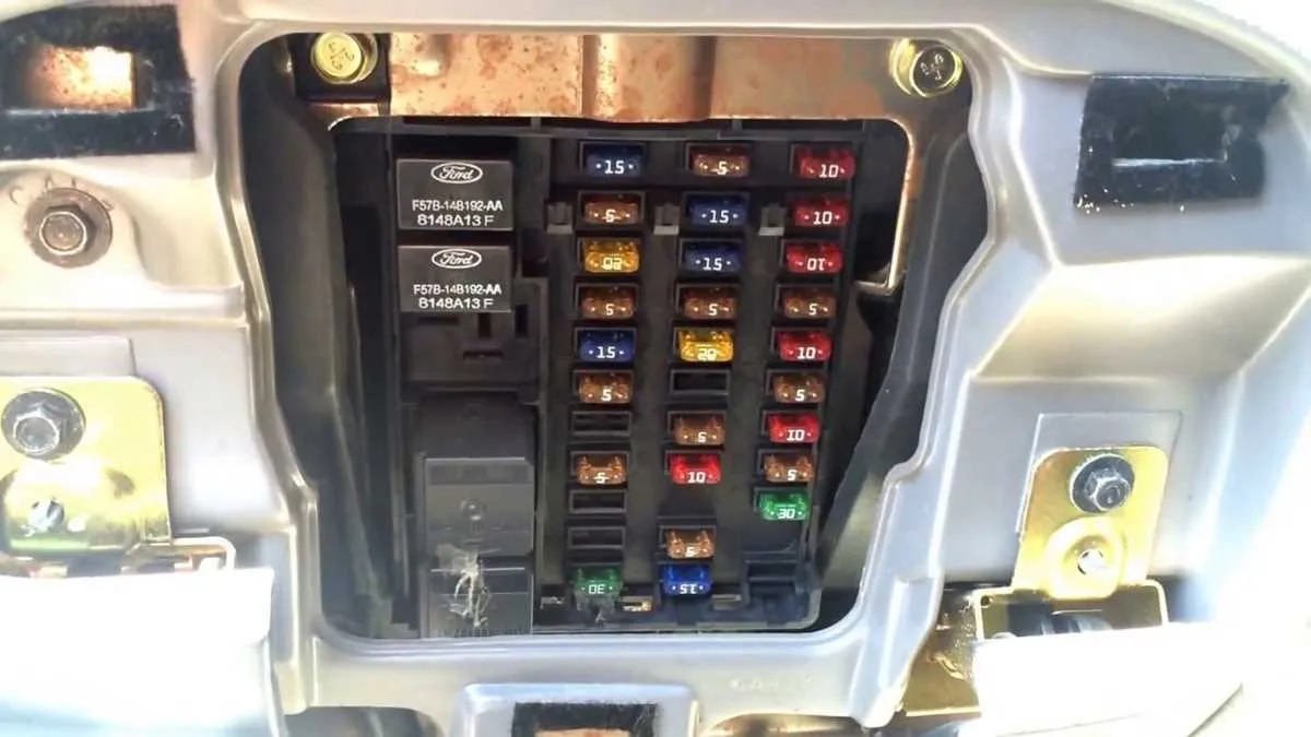
Electrical Relay and Circuit Breaker Layout for 1997 Pickup Truck
To identify and troubleshoot issues with the electrical components, refer to the relay and circuit breaker arrangement located near the engine. This setup controls crucial systems, including lights, ignition, and cooling fans. The layout provides clear identification for each part, ensuring quick and accurate replacements when needed.
Locate the central panel, typically positioned near the battery area. Each section of this configuration corresponds to a specific function. For instance, the upper-left section manages lighting and dashboard instruments, while the bottom-right is designated for critical engine components. Identifying the exact relay for each function will minimize downtime and prevent incorrect replacements.
Key recommendations: Always check the labeling near each component to avoid confusion. Use a multimeter to test for continuity if you’re unsure about the condition of a particular part. Additionally, ensure that the replacement parts match the amperage and voltage requirements specified for each circuit.
If a malfunction occurs, cross-reference the component numbers with your vehicle’s manual to identify the issue accurately. Pay special attention to any burnt or damaged terminals, as these could indicate a more significant problem within the electrical system.
Tip: When replacing a faulty relay, ensure the truck is turned off and the battery is disconnected to avoid any electrical shorts or shocks. Properly install the new part and test it before reassembling the panel.
Understanding Layout and Key Components
Knowing the arrangement of electrical components is essential for diagnosing issues and performing maintenance. The layout of the electrical panel is divided into several key sections that manage various vehicle functions, such as lighting, power windows, and engine management systems. Below are critical areas to focus on when working with the vehicle’s electrical panel.
- Relay Slots: These sections provide control for high-power components like the radiator fan or starter motor. Ensure these are correctly seated to avoid electrical failures.
- Power Distribution: A centralized area that connects multiple circuits to the battery and alternator. If you notice any unusual power drain, inspect this area for damage or corrosion.
- Control Modules: These modules help manage systems like the ignition or fuel injection. Check the connections to prevent system malfunctions.
- Fuses: These act as safeguards, preventing overloads and protecting circuits. Regularly check for blown fuses, and replace them with the same amperage rating to avoid further damage.
Always refer to the component label inside the panel for detailed identification. Understanding the labeling system will help with quicker diagnostics and easier maintenance.
- Color-Coded Labels: Most vehicles use color coding to indicate the amperage of fuses. Green often means lower current, while red and blue are used for higher current circuits.
- Location of Fuses: Specific fuses correspond to different vehicle components like lights or airbags. Keep a map of the fuse layout handy for quick identification.
Keep the area around the electrical panel clean and dry to prevent corrosion or accidental short circuits. Regularly inspect for wear, loose connections, or burnt areas that may signal overheating.
How to Identify and Replace a Blown Fuse in Your F-150

Start by locating the main electrical panel, usually near the driver’s side of the engine compartment. Open the cover and identify the individual components inside. Each one will have a small label or code next to it, indicating its function.
To check for a blown component, visually inspect each part. A blown part will often appear darkened, charred, or broken in the middle. Use a multimeter to confirm continuity if you’re unsure. Set the meter to the continuity mode, and place the probes on both ends of the component. If there’s no beep or reading, it’s time for a replacement.
Before replacing a damaged part, make sure to turn off the engine and disconnect the battery. This reduces the risk of short circuits and ensures safety. Always replace the damaged component with one of the same amperage. Never use a part with a higher rating, as this can cause electrical issues or even damage your vehicle.
To install the new part, gently slide it into the corresponding slot, ensuring it’s fully seated. Close the cover, reconnect the battery, and start the vehicle to test if the problem is resolved. If the issue persists, recheck all components and connections.
Tip: Keep a spare set of components in your toolbox to avoid delays when one blows unexpectedly.
Troubleshooting Electrical Issues with the Power Distribution System in Your Pickup
To resolve electrical problems, start by checking the main relay panel, which controls power flow to vital components. Often, corrosion or a loose connection can cause intermittent failures. Use a multimeter to verify if voltage is properly reaching the terminal points. If the voltage readings are off, inspect the wiring for any visible damage or fraying. Pay close attention to ground connections, as a poor ground can cause erratic behavior.
If a particular component fails to operate, cross-check the corresponding terminal in the distribution unit. Confirm that the circuit isn’t overloaded or showing signs of a short. If necessary, use a test light to check continuity through the fuses. A blown element typically points to an issue like a short circuit or a fault in a connected device. Replace any faulty parts with the same rating to avoid further issues.
Key steps:
- Check relay continuity with a multimeter.
- Inspect wiring for any wear or signs of burning.
- Ensure all grounding points are clean and secure.
- Replace any damaged or blown parts with exact replacements.
When troubleshooting, always disconnect the battery to prevent accidental short circuits while working with electrical components.