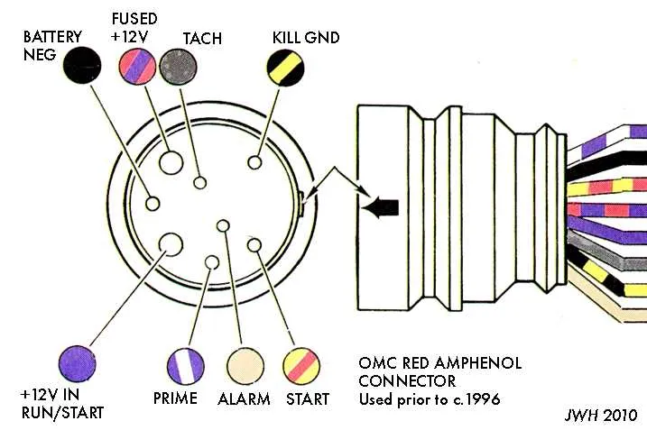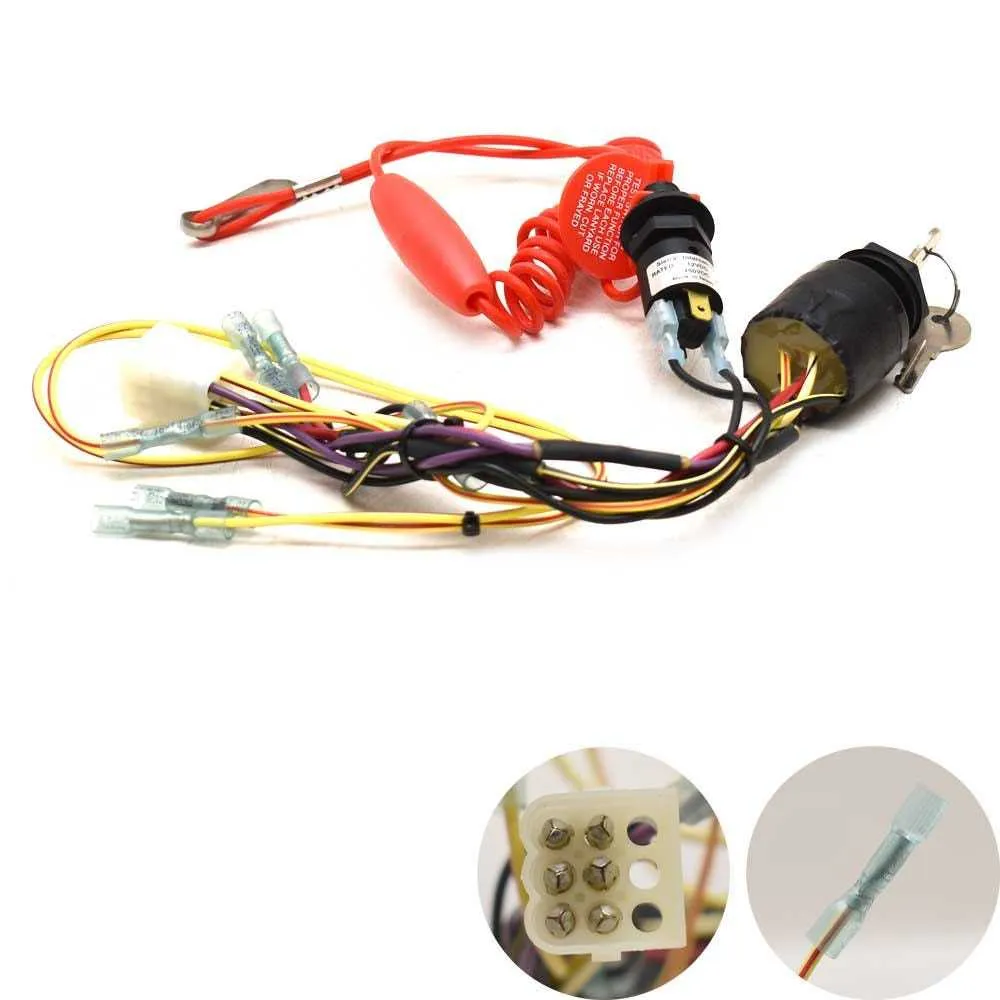
If you’re aiming to set up a reliable start-up mechanism for your watercraft’s electrical setup, a well-planned and correctly connected system is crucial. Understanding the correct placement of terminals and ensuring proper contact with the engine’s power source can save time and prevent malfunction during operation.
Start by confirming the power source connection to your starter motor. It’s vital to ensure that the battery’s positive terminal is securely linked to the starter motor’s input, with an efficient ground path established to complete the circuit. Pay attention to the placement of the protective fuse, which shields the entire system from unexpected surges.
The key to avoiding issues lies in following a structured layout for the power flow. Ensure each component, such as the relay and starter solenoid, is correctly linked to both the power and ground paths. Misplaced wiring can lead to intermittent starting problems or complete failure to power up the engine.
Additionally, confirm that the connection for the power distribution panel is correctly routed, ensuring each switch or control sends the right signal at the appropriate moment. Overlooking this can result in unresponsive controls or damage to sensitive equipment, reducing the longevity of your system.
Wiring Guide for Marine Engine Start System
For a reliable engine start-up system, ensure proper connections between the key component and its relay circuit. The primary element in this setup should be connected to the power source through a fused line to prevent overload. The secondary part of the circuit should engage the solenoid, which activates the starter motor upon receiving a signal.
Ensure the correct grounding of the main unit to avoid issues with the electrical flow. For the control side, use a heavy-duty switch designed to handle the amperage. The terminal marked “C” should be connected to the battery, while the “S” terminal will route to the solenoid to trigger the motor’s activation. The “I” terminal should link to the ignition coil, supplying power when needed.
When dealing with a multi-position system, each position should correspond to a specific function, like accessory power, engine start, and kill circuit. Double-check all wire connections for corrosion and fraying, as this can cause system failure or unreliable performance.
For added protection, install a fuse on the power input line. If the unit does not function as expected, inspect the fuse, check the solenoid’s responsiveness, and confirm the connections are secure. Regular maintenance and inspection are key to preventing failure in the electrical circuit and ensuring consistent operation.
Understanding the Basic Components of a Marine Engine Start System

The primary elements of a marine engine start system include the power source, the key mechanism, the starter relay, and the safety components. Each part plays a specific role in ensuring proper activation and operation of the motor.
The power source, typically the battery, supplies the necessary electrical current for engine activation. It is critical to ensure the battery is fully charged and in good condition, as any power loss can prevent proper engine startup.
The key mechanism, or the user interface, is the part where you engage to initiate the starting process. It’s essential to verify the integrity of the contacts within this component. Over time, they can wear out or corrode, leading to unreliable performance.
The starter relay is an essential component that connects the battery power to the motor’s starter. It acts as a switch that transmits current when activated. Problems with the relay, such as corrosion or malfunction, can cause delayed starts or prevent activation altogether.
Safety elements, including the lanyard kill switch or safety fuses, are integral for preventing accidental start-ups or ensuring the engine cuts out when necessary. Ensuring these systems are functioning correctly will reduce the risk of engine damage or safety hazards.
In addition to these key components, regular maintenance and checks are necessary to ensure all parts function as intended. Connections should be clean, tight, and free from corrosion to avoid power loss or failure in the starting process.
Step-by-Step Guide to Connecting the Engine Starter Control
To properly set up the engine starter control, follow this detailed procedure to ensure correct functionality and safety. Each connection must be precise and secure to avoid electrical malfunctions.
- Preparation: Disconnect the battery before starting any work to prevent accidental shorts or electrical shocks.
- Identify Components: Locate the terminal connections for the key-operated device. These typically include terminals for power input, starter signal, and ground connections.
- Power Input: Connect the positive wire from the power supply to the main terminal. Ensure the wire is thick enough to handle the current without overheating.
- Starter Relay: Attach a wire from the starter signal terminal to the relay. This wire will trigger the engine’s starter mechanism when the device is turned to the “start” position.
- Ground Connection: Secure the ground wire to the negative terminal of the system. This is crucial for the control mechanism to operate correctly.
- Safety Check: Confirm all wires are firmly connected, and ensure no exposed wires are at risk of touching other components, which could lead to a short circuit.
- Test Functionality: Reconnect the battery and test the device by turning the key to the start position. The engine should engage immediately, with no delays or unusual sounds.
- Final Inspection: Inspect all connections one final time, ensuring there are no loose terminals or frayed wires that could cause issues later.
By following these steps precisely, you ensure the proper operation of the engine starting system, reducing the risk of electrical failures and extending the longevity of the components.
Troubleshooting Common Electrical Connection Issues
If the engine fails to start despite turning the key, check the power source to ensure the battery has sufficient charge. A weak or dead battery is often the primary cause of electrical failure. Test voltage using a multimeter–12.6V indicates a full charge, while 11V or lower means the battery needs charging or replacement.
Next, verify the connections between components. Corrosion or loose terminals on the battery can disrupt power flow. Clean all connectors with a wire brush and ensure they’re tightly secured to prevent intermittent contact. Inspect the ground connection–poor grounding can prevent proper operation.
Another frequent issue is a malfunctioning key mechanism. When turning the key, check if there’s resistance or an abnormal feeling. This could indicate worn-out internal contacts. If necessary, disassemble and clean or replace the faulty component. A damaged component often leads to a failure to transmit current to the engine’s starter.
If the system turns on, but the engine doesn’t respond, inspect the circuitry for continuity. A break in the wiring or a damaged relay might block the current flow, preventing activation. Test the continuity with a multimeter and replace any defective parts.
Fuses should also be checked. If the system powers up but doesn’t crank, the fuse may be blown. Locate and replace the fuse with the correct amperage, as using a higher or lower value can cause further issues.
Lastly, test any security systems integrated into the setup. If there’s an anti-theft module or a kill switch, verify that it’s disengaged or properly activated. These systems can prevent the engine from starting if they’re not in the correct state.