If you’re troubleshooting electrical issues in your Honda model, the fuse panel layout is a critical resource. Understanding the precise locations of various circuits within the power distribution unit will save you significant time during repairs. It’s essential to consult the specific wiring chart to ensure you’re addressing the right components without causing damage to the system.
The power distribution unit under the dashboard and engine bay plays a central role in managing current flow to vital systems. Each section corresponds to a specific function, from lighting to engine management. Familiarize yourself with the components connected to each section for effective diagnosis and replacement of faulty parts.
Accessing the right layout allows you to pinpoint blown links or short circuits with ease. Be sure to use a reliable source that outlines both the internal and external configurations for a complete understanding. Once you have the correct chart, follow the wiring paths systematically to ensure a seamless fix to your electrical issues.
Electrical Component Layout for 1998 Honda Model

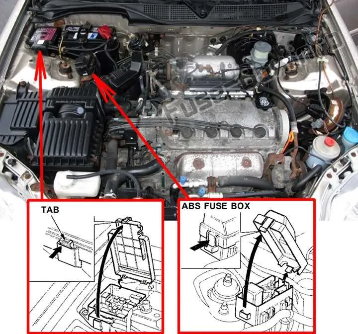
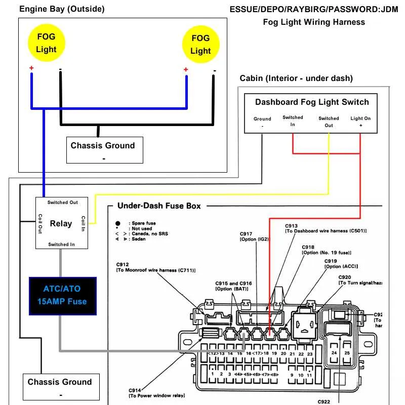
To ensure proper functioning of the electrical system, refer to the schematic for the central distribution point. The primary units are located under the dashboard on the driver’s side, and the secondary ones are positioned in the engine compartment near the battery. Each component is designed to manage specific electrical functions, so understanding their placement is crucial for troubleshooting.
Main Unit: Inside the cabin, this panel handles interior lighting, air conditioning, and various sensors. If there is an issue with any of these, check for blown connections or faulty relays. Commonly, the issue lies with the 10A or 15A circuits which protect critical internal features.
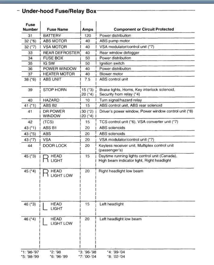
Engine Compartment: The external relay station controls high-power circuits, including the ignition, headlights, and windshield wipers. These are typically larger in size and often feature 20A to 30A fuses. The most frequently malfunctioning components include the ignition and power steering relay, both of which can cause driving difficulty if interrupted.
Examine the connections for signs of wear or corrosion, especially around high-traffic components like the alternator or cooling fans. For accurate identification of the components and their respective amperage ratings, consult the manual for the full layout and operational guide.
Note: Always ensure that any replacements are rated for the same voltage and amperage to avoid potential damage or overheating issues in the system.
Understanding the Layout of the 1998 Honda Civic Fuse Box
For quick and easy troubleshooting, always start by identifying the correct placement of each circuit. This helps to avoid unnecessary disassembly. The central unit is located under the dashboard on the driver’s side, typically beneath the steering column. Inside, the arrangement is quite logical, with fuses arranged in rows for quick identification. Each row corresponds to specific electrical components, such as the lighting system, radio, and power windows.
In this configuration, the uppermost section houses the larger fuses for high-power systems, while the smaller ones handle less demanding circuits like sensors and auxiliary components. Ensure that you check the cover for a legend, which will typically map the fuse layout to the specific devices or systems they protect.
Important tip: Always replace a blown fuse with the correct amperage to avoid overloading other systems. Double-check the fuse’s rating before installation.
Keep in mind that while the interior panel is the primary access point, there may also be an auxiliary compartment near the engine bay, typically on the driver’s side, for additional fuses that control engine-related systems. Always inspect both compartments when performing electrical diagnostics.
How to Identify and Replace Fuses in the 1998 Civic

Start by locating the electrical panel, typically positioned under the dashboard or near the engine bay. Refer to the vehicle’s manual to find the exact placement of the fuse holders.
To identify a blown component, inspect the wire inside the piece. If the wire appears broken or burnt, that part is defective.
Follow these steps for replacing damaged components:
- Turn off the ignition and remove the key from the ignition switch to avoid electrical shock.
- Use a fuse puller or small pliers to gently remove the faulty item.
- Ensure the new component matches the amperage rating, which is typically marked on the side of the fuse or in the vehicle’s manual.
- Insert the replacement part into the holder securely and check that it fits snugly.
- Test the electrical system to confirm proper functionality.
If the problem persists after replacing the blown part, verify the power supply for underlying issues or consult a technician.
Common locations to find the electrical panels are:
- Driver-side dashboard (near the left footwell)
- Engine compartment (usually near the battery)
For better longevity and system reliability, replace any faulty components with parts that match the vehicle’s specifications. Using incorrect parts can lead to further damage or malfunctions.
Common Electrical Issues Linked to Fuse Box Problems

One of the most frequent problems seen in older vehicles is malfunctioning circuits caused by faulty connections in the electrical panel. Symptoms such as sudden loss of power to the dashboard, non-functioning lights, or erratic behavior from various systems (e.g., wipers, radio) are clear indicators of issues originating here.
Corrosion on connectors is a prime culprit, leading to poor contact between wires and terminals. This often results in intermittent or complete failure of certain functions, like headlights or signals. Ensuring that all terminals are clean and free from moisture can prevent these issues from escalating.
Another problem is blown relays or fuses. When a specific function stops working (like air conditioning or interior lights), check the relevant components within the electrical panel. If fuses appear intact, but there’s still a malfunction, it’s worth testing the relays as well.
Overheating is also a concern, particularly in areas where the electrical wiring is exposed to prolonged use or high temperatures. Overloaded circuits can cause wires to melt, damaging the system. Always be cautious when replacing wires–use the correct gauge and ensure no excessive strain is placed on any single circuit.
Finally, when troubleshooting, make sure the ground connections are secure. Loose or damaged ground wires can cause the system to act unpredictably, often manifesting as power surges or the failure of multiple electrical systems at once. These should be inspected regularly to ensure reliable operation.