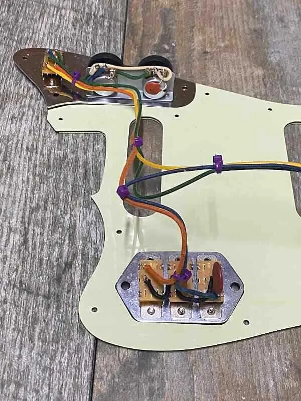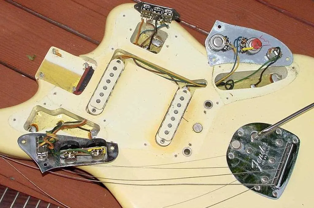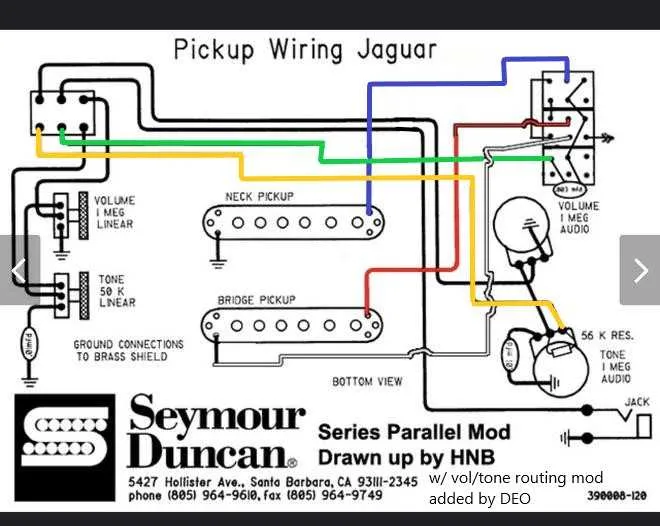
If you’re looking to modify or repair your electric guitar’s circuitry, it’s crucial to understand the specific connections that make up the signal flow. Start by checking the pickup selector switch wiring, ensuring each contact is correctly routed to avoid interference or signal loss. Pay close attention to the ground connections to prevent unwanted hums or buzzing during performance.
Focus on the pot connections: the potentiometers control the tone and volume. Double-check the capacitor’s placement within the circuit, as this directly influences the tone quality. A correctly wired potentiometer can significantly impact the tonal response, allowing for precise control over your instrument’s output.
For those looking to implement custom features, consider experimenting with series or parallel wiring for your pickups. This approach alters the magnetic field interaction, which can result in a more aggressive or warmer sound, depending on your choice. Use reliable connectors and solder joints to ensure durability and maintain the integrity of your instrument’s performance.
Test the circuit before finalizing your setup. Use a multimeter to verify continuity and check that there are no shorts between adjacent components. Ensuring the accuracy of each connection will help avoid issues during performance, making this an essential step in the modification process.
Electric Circuit Overview for the Iconic Guitar Model
For optimal performance of the electrical setup, ensure all components are correctly connected and grounded. Start by verifying the positions of the switches, ensuring the series/parallel wiring is functioning as intended. The neck and bridge pickups should be independently controlled, with clear separation between the two for precise tone shaping. The tone control should operate smoothly through the full range without causing any abrupt shifts or drops in signal strength.
Pickup Selector – Use a three-way switch for seamless transitions between the two pickups. This switch is responsible for routing the signal, with each position corresponding to either pickup or both in combination. Proper insulation is essential to avoid short circuits, particularly around the switch terminals.
Capacitor Placement – Ensure the capacitor is placed across the tone control circuit. This will manage the high-frequency roll-off, allowing for smoother tone adjustments. If your setup lacks clarity or becomes too muffled when rolling back the tone, consider experimenting with different capacitor values to fine-tune your sound.
Grounding Method – Grounding should be carefully executed to prevent hum or noise interference. Each metal part, including pots, switches, and jacks, must have a dedicated ground connection, ideally linked to a single point on the circuit. Use a star grounding configuration to minimize loop interference.
Potentiometer Calibration – Verify the resistance of each potentiometer, ensuring they are suitable for the intended tonal control range. Typically, a 250k pot is used for the tone control, while a 1M pot is preferred for volume adjustment. Make sure the pots have a smooth and consistent sweep.
Understanding the Pickup Layout
Ensure correct orientation of the pickups by first confirming the polarity. The neck and bridge units should be installed with the right coil direction to avoid phase cancellation. When switching between the pickups, it’s essential to utilize the toggle switch for proper engagement, ensuring each position leads to the intended combination of signal routes. The tone and volume controls are directly linked to each pickup, so check their connections to avoid issues with response. For optimal output, consider using a treble bleed circuit on the volume pot, which helps preserve high frequencies when turning down the gain. Double-check the grounding of the components to prevent unwanted hum or noise.
When altering the circuit, ensure each connection is solid, particularly between the pots and the output jack. The most common problem in setups like this is faulty solder joints or loose connections, which can lead to inconsistent performance. Keep the wiring layout as clean as possible to reduce interference. Pay close attention to the correct placement of the capacitor for tone adjustments, and test each setting before finalizing the installation. If upgrading, using higher-quality components can significantly enhance the overall sound clarity and reliability.
How to Rewire a Fender Jaguar for Custom Sounds

Start by removing the pickguard carefully to expose the electronics. Use a soldering iron to detach the existing components. If you plan to add different pickups or switches, you need to determine the layout that suits your desired tone modifications.
Next, consider upgrading to a more flexible potentiometer setup. Swap the standard 250k or 500k pots with ones offering more resistance for greater control over the tone. This will give you more room to shape midrange and high frequencies, which are crucial for creating custom sounds.
Replace the toggle switch with a 3-way switch or an enhanced push-pull switch to allow for additional tonal variations. When doing this, make sure to check the switch’s compatibility with the other components to avoid circuit overloads.
Install new capacitors with different values to change the frequency range that your guitar responds to. Smaller capacitors (e.g., 0.022uF) allow for sharper, crisper tones, while larger values (e.g., 0.047uF) provide a smoother, warmer sound, ideal for jazz or classic rock styles.
Use shielded wiring to reduce unwanted hum and interference. If you’re aiming for an especially clean tone, ensure that all connections are properly grounded to eliminate any noise from other electronics in the area.
Finally, reassemble the components and check the functionality of each part before securing the pickguard back into place. Test the instrument by plugging it into an amp and tweaking each knob to explore the full range of new custom sounds.
Common Electrical Issues and Solutions for Fender Jaguar

To address frequent electrical problems, begin by verifying the grounding of all components. Poor grounding is a common cause of signal loss and hum. Ensure that all ground wires are securely attached to the body and that they connect properly to the jack and pots.
- Issue: Volume control not responsive
- Solution: Inspect the potentiometer for wear or dirt. Clean the pot or replace it if it shows significant damage. Check for loose connections to the pot’s lugs.
- Issue: Switch not functioning correctly
- Solution: Clean the switch contacts with a contact cleaner. If the problem persists, check for broken solder joints or worn-out switch parts that may need replacement.
- Issue: Excessive hum or buzzing
- Solution: Confirm that the shielded cables are intact and properly connected to the ground. Replace any damaged cables. Ensure that the pickups are grounded well.
- Issue: Incorrect pickup selection
- Solution: Double-check the connections between the pickups and selector switch. Ensure the switch is wired correctly, following the intended configuration.
- Issue: Loss of tone control
- Solution: Inspect the tone pot and check the capacitor for damage. If the pot is not functioning, consider replacing it. Also, verify that the capacitor is correctly soldered to the pot.
- Issue: Intermittent signal drop
- Solution: Check for cold solder joints at the input jack and throughout the circuit. Resolder any joints that appear cracked or brittle.