
The 2-wire oxygen (O2) sensor is an integral component of modern vehicle emissions control systems. The sensor works by measuring the oxygen content in the exhaust gases and transmitting this information to the engine control unit (ECU). This allows the ECU to adjust the air/fuel mixture to optimize combustion and reduce harmful emissions.
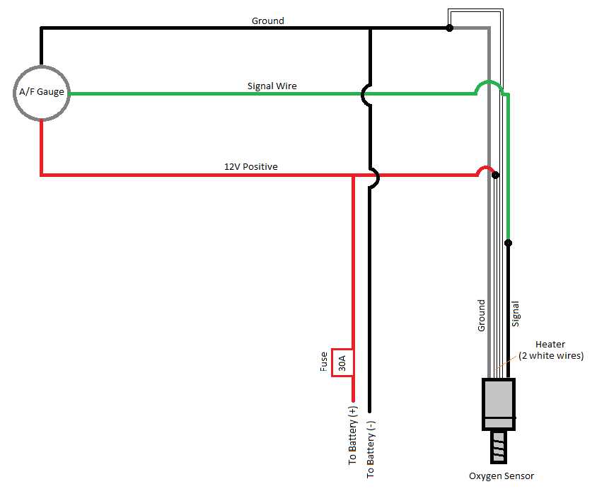
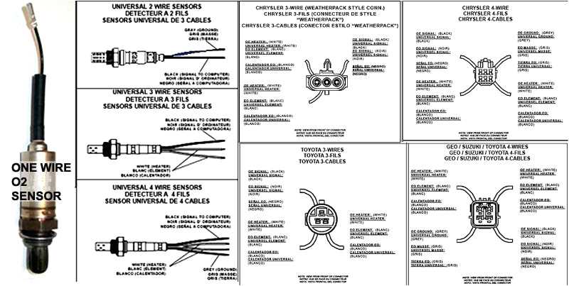
The wiring diagram for a 2-wire O2 sensor typically shows the two wires: a signal wire and a ground wire. The signal wire is responsible for transmitting the oxygen content information to the ECU, while the ground wire provides the necessary electrical reference. It’s important to follow the correct wiring diagram when installing or replacing a 2-wire O2 sensor to ensure proper operation and compatibility with the vehicle’s ECU.
Additionally, the wiring diagram may also include other components, such as a heating element or a heater circuit. Some 2-wire O2 sensors have a built-in heater to bring the sensor up to operating temperature quickly, which improves accuracy and responsiveness. The heating element is typically powered by a separate circuit, and the wiring diagram will indicate the connections to the power supply.
In summary, understanding the wiring diagram for a 2-wire O2 sensor is crucial for proper installation and operation. It allows for the correct connection of the signal and ground wires, as well as any additional components, such as a heating element. By following the recommended wiring diagram, you can ensure the accurate transmission of oxygen content data to the vehicle’s ECU, leading to optimal engine performance and reduced emissions.
How to Wire a 2-Wire O2 Sensor: A Comprehensive Wiring Diagram Guide
Wiring a 2-wire O2 sensor can be a straightforward process if you follow the correct steps. This comprehensive wiring diagram guide will help you understand the procedure and ensure a successful installation.
Gather the Necessary Tools and Materials
Before you begin, make sure you have all the necessary tools and materials. You will need a wire stripper, crimping tool, electrical tape, soldering iron (optional), and a wiring diagram for your vehicle’s specific O2 sensor.
Identify the Sensor Wires
The first step is to identify the wires on the O2 sensor connector. There are typically two wires, a signal wire and a ground wire. The signal wire is responsible for sending the oxygen sensor’s voltage signal to the engine control module (ECM) or powertrain control module (PCM).
Prepare the Wires
To prepare the wires for connection, use a wire stripper to remove a small section of insulation from both the signal wire and the ground wire. This will expose the metal conductor inside.
Connect the Wires
Using the wiring diagram for reference, connect the signal wire to the appropriate wire on the vehicle’s ECM or PCM. This connection is typically made by crimping an electrical connector onto the wires. Alternatively, you can solder the wires together and secure the connection with electrical tape.
Next, connect the ground wire to a suitable ground point on the vehicle. This can be a metal bracket or the vehicle’s chassis. Ensure the connection is secure to avoid any potential grounding issues.
Test the Sensor
Once the wires are connected, it’s important to test the O2 sensor to ensure it’s functioning correctly. Start the engine and use a multimeter to measure the voltage output of the sensor. The voltage should fluctuate between approximately 0.1V and 0.9V, indicating normal sensor operation.
Secure the Wiring
After confirming the sensor is working properly, secure the wiring using zip ties or electrical tape. This will prevent the wires from coming loose or getting damaged while driving.
Final Checks
Lastly, double-check all the connections and ensure everything is properly insulated. Test the sensor again to verify its performance. If everything is working as expected, you have successfully wired a 2-wire O2 sensor.
Remember, it’s crucial to follow the wiring diagram specific to your vehicle’s O2 sensor. Incorrect wiring can lead to erroneous readings and potential engine performance issues. If you’re unsure about any step of the process, consult a professional mechanic or refer to your vehicle’s service manual for guidance.
Understanding the Basics of a 2-Wire O2 Sensor
When it comes to ensuring optimal engine performance and reducing emissions, an oxygen (O2) sensor is an essential component of a vehicle’s exhaust system. A 2-wire O2 sensor is a specific type of sensor that plays a crucial role in monitoring the air-fuel ratio and providing feedback to the engine control unit (ECU).
A 2-wire O2 sensor consists of two wires: one for the signal wire and another for the ground wire. The signal wire is responsible for transmitting the sensor’s output voltage to the ECU, while the ground wire provides a reference point for the sensor’s operation. The ECU uses the voltage signal from the sensor to make necessary adjustments to the fuel mixture, ensuring optimal combustion.
Typically, a 2-wire O2 sensor uses a zirconia element to detect the oxygen content in the exhaust gases. The zirconia element operates by generating a voltage signal that is proportional to the difference in oxygen concentrations between the exhaust gas and the reference atmosphere. This voltage signal is then transmitted through the signal wire to the ECU.
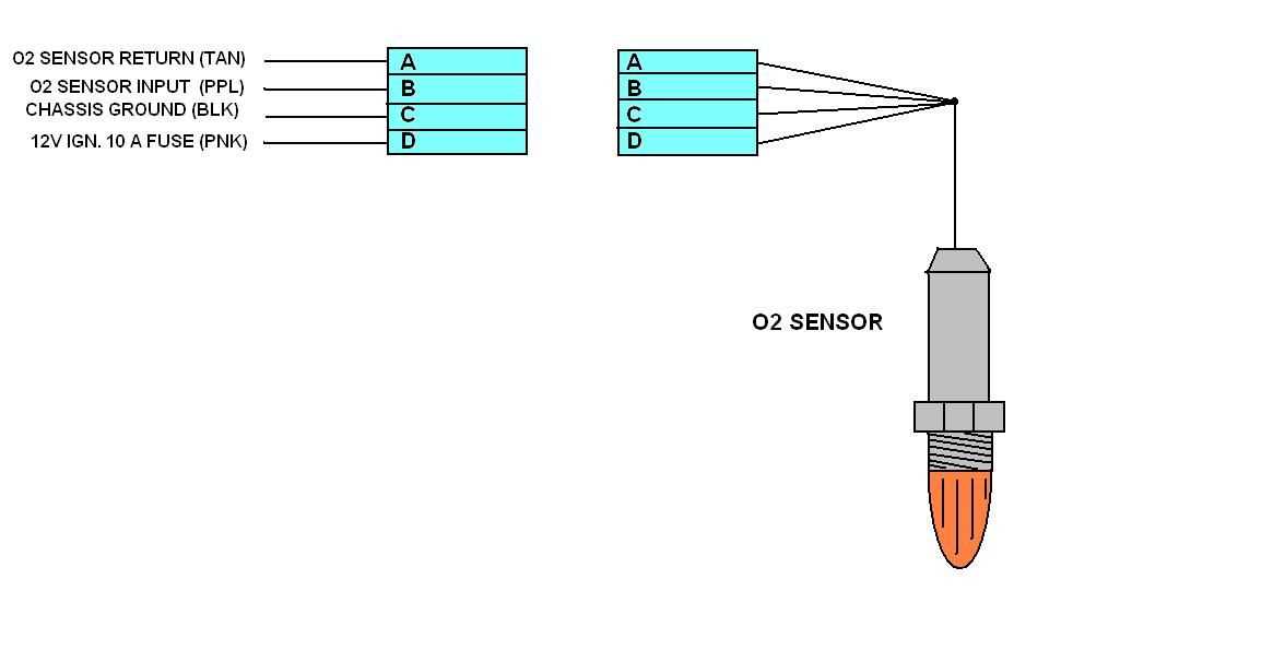
It’s important to note that the wiring configuration of a 2-wire O2 sensor may vary depending on the vehicle’s make and model. Some sensors may have different colored wires, but the general principle remains the same: one wire for the signal and one wire for the ground. Therefore, it’s crucial to consult the vehicle’s specific wiring diagram or manual to correctly identify the wires and their corresponding functions.
In summary, understanding the basics of a 2-wire O2 sensor is crucial for maintaining optimal engine performance and reducing emissions. By accurately monitoring the air-fuel ratio and providing feedback to the ECU, the sensor helps the engine make necessary adjustments to ensure efficient combustion. It’s important to consult the vehicle’s wiring diagram or manual to correctly identify the signal and ground wires of the sensor.
Step-by-Step Guide: Wiring a 2-Wire O2 Sensor

Wiring a 2-wire O2 sensor is a straightforward process that requires a few basic tools and some knowledge of electrical connections. This step-by-step guide will walk you through the necessary steps to complete the wiring successfully.
Step 1: Gather the Materials
Before starting the process, make sure you have all the necessary materials on hand. This includes a 2-wire O2 sensor, wire strippers, crimping tool, electrical tape, and a wiring harness, if applicable.
Step 2: Identify the Wires
Take a close look at your 2-wire O2 sensor and identify the two wires. Typically, one wire will be black, and the other will be white. The black wire is the ground wire, and the white wire is the signal wire.
Step 3: Prepare the Wires
Using your wire strippers, remove about 1/4 inch of insulation from the ends of both wires. This will expose the bare wire for the next step.
Step 4: Connect the Wires
Take the ground wire (black) and connect it to a suitable ground location on your vehicle. This can be a bolt or screw that securely connects to the vehicle’s chassis. Use your crimping tool to secure the connection.
Next, take the signal wire (white) and connect it to the corresponding wire on your wiring harness. Again, use your crimping tool to ensure a secure connection.
Step 5: Insulate the Connections
To protect the connections and prevent any potential electrical issues, wrap each connection with electrical tape. This will provide insulation and help keep the wires in place.
Step 6: Test the Connection
Once the wiring is complete, start your vehicle and test the connection. Make sure the O2 sensor is functioning correctly and providing accurate readings.
Following these steps will ensure that you properly wire a 2-wire O2 sensor. Always refer to the manufacturer’s instructions for specific wiring diagrams and precautions related to your particular vehicle and O2 sensor model.
Choosing the Correct Wire Colors for a 2-Wire O2 Sensor
When it comes to installing or replacing a 2-wire O2 sensor, it is crucial to choose the correct wire colors to ensure proper functionality. The two wires on an O2 sensor are typically color-coded, with one being the signal wire and the other being the ground wire. It is essential to match these wire colors correctly to avoid any wiring-related issues.
The most common wire colors for a 2-wire O2 sensor are black and white. The black wire is usually the signal wire, while the white wire is the ground wire. However, it is important to note that wire colors may vary between different vehicle manufacturers and models. Therefore, it is always recommended to refer to the specific wiring diagram for the vehicle you are working on to determine the correct wire colors for the O2 sensor.
As a general rule of thumb, the signal wire is typically the one that connects to the vehicle’s engine control module (ECM). This wire is responsible for transmitting the O2 sensor’s output voltage or current to the ECM, which uses this information to adjust the fuel mixture for optimal engine performance. The ground wire, on the other hand, is connected to the vehicle’s chassis or ground point and serves as a reference point for the sensor’s measurements.
If you are unsure about the wire colors for your 2-wire O2 sensor, it is recommended to consult the vehicle’s service manual or reach out to the manufacturer for clarification. Using the wrong wire colors can lead to incorrect sensor readings and potentially cause issues with the engine’s performance and emissions control system. Taking the time to properly identify and match the wire colors will ensure a successful installation or replacement of the 2-wire O2 sensor.
Common Mistakes to Avoid When Wiring a 2-Wire O2 Sensor
Wiring a 2-wire O2 sensor may seem like a simple task, but there are some common mistakes that people make which can lead to inaccurate readings or even damage to the sensor. To ensure proper installation and functioning of your O2 sensor, it is important to avoid these mistakes:
Wrong wire connections
One of the most common mistakes is connecting the wires to the wrong terminals. The 2-wire O2 sensor has a signal wire and a ground wire. It is crucial to identify these wires correctly and connect them to the corresponding terminals. Mixing up the wires can lead to incorrect readings and affect the performance of the sensor.
Improper wire insulation
Another mistake to avoid is improper wire insulation. The O2 sensor wires should be properly insulated and protected from external factors like heat, moisture, and physical damage. Using appropriate wire insulation materials and techniques can prevent potential problems caused by exposed wires, such as short circuits or faulty readings.
Insufficient cable length
Ensuring that the O2 sensor has sufficient cable length is essential for proper installation. Insufficient cable length can lead to tension and strain on the wires, which can result in damage over time. It is recommended to have enough extra cable length to allow for proper routing and flexibility without putting excessive stress on the sensor’s wiring.
No use of dielectric grease
Dielectric grease is a protective coating that can prevent moisture and corrosion from affecting the connection points of the O2 sensor. Not using dielectric grease or not applying it properly can lead to poor electrical connections and eventually damage the sensor. It is important to apply a small amount of dielectric grease to the sensor’s connectors to ensure a secure and long-lasting connection.
By avoiding these common mistakes when wiring a 2-wire O2 sensor, you can ensure accurate readings and a longer lifespan for your sensor. It is always recommended to refer to the manufacturer’s instructions and guidelines for proper installation to avoid any potential issues. Taking the time to install and wire the sensor correctly can save you from costly repairs and improve the overall performance of your vehicle.
Important Tips for Installing a 2-Wire O2 Sensor
Installing a 2-wire oxygen sensor is a relatively straightforward process, but there are a few important tips to keep in mind to ensure proper installation and optimal performance.
1. Familiarize Yourself with the Sensor
Before starting the installation process, take the time to familiarize yourself with the specific sensor you are working with. Read the manufacturer’s instructions and make sure you have the correct sensor for your vehicle.
2. Prepare the Exhaust System
Prior to installing the sensor, ensure that the exhaust system is cool to the touch. Working with a hot exhaust can be dangerous and may result in burns. Additionally, it is important to clean the area where the sensor will be installed to ensure a proper connection.
3. Identify the Correct Wires
Identifying the correct wires is crucial when installing a 2-wire oxygen sensor. The sensor will typically have two wires – one black and one white. The black wire is usually the sensor ground, while the white wire is the signal wire. Consult the wiring diagram or the vehicle’s service manual to ensure that you are connecting the sensor correctly.
4. Use Proper Tools and Techniques
When removing the old sensor or installing the new one, it is important to use the proper tools and techniques. Avoid using excessive force, as this can damage the sensor or the exhaust system. Use a wrench or socket that fits the sensor securely to ensure a tight and secure connection.
5. Test the Sensor

After the installation is complete, it is recommended to test the sensor to ensure it is functioning properly. Start the engine and monitor the sensor readings using a scan tool or an OBD-II code reader. If the readings are within the expected range, the sensor is properly installed. If the readings are abnormal, double-check the wiring connections and consult a professional if needed.
By following these important tips, you can ensure a successful and reliable installation of a 2-wire oxygen sensor. Remember to always consult the manufacturer’s instructions and the vehicle’s service manual for specific guidelines and recommendations.