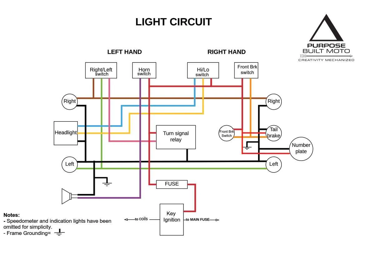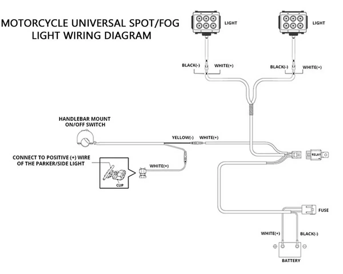
To avoid costly repairs and ensure your bike runs smoothly, mastering the electrical components is essential. Start by locating the key parts of the electrical system, such as the battery, ignition system, and various sensors. Knowing where each wire connects can help you troubleshoot any issues with ease.
For accurate diagnosis, refer to the schematic that outlines the specific wiring connections and components of the engine, lights, and control units. This map will help you identify which circuits are linked to essential functions like the fuel system, starter motor, and charging unit.
Regular inspection of these connections can prevent power failures. Ensure that all contacts are clean and free of corrosion, especially those at the battery terminals. Checking the voltage output across various components also provides valuable insight into the overall health of your bike’s electrical system.
Electrical Circuit Overview of Two-Wheeled Vehicles
Ensure the correct identification of components before attempting repairs or modifications. The power distribution system, including the battery, ignition switch, and fuses, must be thoroughly understood to avoid damaging sensitive parts. The stator, alternator, and rectifier are essential for charging the battery and providing power to various electrical units.
Start by checking the connection of the ignition coil to the spark plug. A poor connection here can result in weak or no spark. Verify the ground connections; without proper grounding, electrical components may malfunction. The signal system should be examined to ensure continuity between the indicator lights, relays, and switches. If you notice dim lighting or malfunctioning signals, inspect the wiring leading to the light assembly and the switch itself.
Critical connections: The engine kill switch must be integrated correctly with the ignition system to prevent any electrical faults. In addition, check the regulator and rectifier unit for any signs of wear or overheating. These parts are responsible for converting AC current to DC, essential for battery charging and system stability.
Tip: For troubleshooting, use a multimeter to check for voltage consistency. If there are fluctuations or irregularities in power delivery, trace the wiring paths back to their source, ensuring that no wires are frayed or disconnected. Always refer to the model-specific service manual for precise wiring information to prevent confusion during the repair process.
Understanding the Main Components in a Two-Wheeled Vehicle Electrical Setup
Focus on the following primary elements when working with the electrical system of a two-wheeled vehicle:
- Battery: Powers the entire electrical circuit, providing voltage to start the engine and support accessories. It requires regular maintenance to avoid discharging.
- Ignition Coil: Converts low voltage into high voltage to create the spark needed for combustion. Typically located near the engine, it is crucial for engine starting.
- Regulator/Rectifier: This component ensures that the voltage coming from the alternator is stable and correct for the battery and electrical devices. It converts alternating current (AC) into direct current (DC).
- Fuses: Protect electrical circuits by breaking the connection when there is an overload or short circuit. Always check fuses before troubleshooting other components.
- Alternator: Generates electricity to recharge the battery while the engine is running. If it fails, the battery will eventually lose charge.
- Starter Relay: Acts as a switch to connect the battery to the starter motor when the ignition button is pressed.
Ensure all components are correctly connected to avoid malfunction. Use a multimeter to test for continuity and voltage in each part to ensure optimal performance.
How to Read a Motorcycle Wiring Diagram for Troubleshooting
Start by identifying the key components and their connections, typically marked with symbols. Each component (such as the battery, ignition, or lights) will have a unique representation. Focus on the positive and negative terminals to trace the flow of electricity.
Check for color codes next to the lines, which represent the wires. These will help you identify the path of power or ground in the system. Red wires usually indicate positive current, while black wires often show ground or negative connections.
Locate the power source, which is usually the battery or a fuse. Ensure there is a clear path from the power supply to each device, looking for any breaks, shorts, or misconnected terminals that might disrupt the circuit.
For troubleshooting, compare the layout of the electrical system to the actual setup. If a device isn’t working, start by tracing the wire back to the power source, checking for continuity with a multimeter. If you find a break, repair or replace the affected wire or component.
Note that ground points are critical. Any loose or corroded ground connections can lead to malfunctioning systems, so ensure all grounding points are clean and secure.
Finally, review switches and relays. These control the flow of current and can malfunction, cutting power to various parts of the system. Inspect them for wear and proper operation.
Identifying Common Electrical Issues and How to Fix Them

If your engine is not starting, inspect the battery connections first. Loose or corroded terminals are often the culprit. Clean the connections with a wire brush and tighten them securely to ensure a solid contact.
Flickering headlights can be a sign of a failing alternator. Test the voltage output at the battery. If the voltage drops below 12.5V while the engine is running, replace the alternator or inspect the charging system for loose connections.
Frequent blown fuses usually indicate a short circuit. To pinpoint the issue, check for frayed or exposed wires that might be touching metal parts. Replace any damaged components and re-test the system with a new fuse.
If you experience intermittent electrical failures or weak power, check the ground connections. Corroded or loose grounds can disrupt the flow of current. Clean or replace the ground wire to restore consistent electrical flow.
Start relay failure can prevent the engine from turning over. Measure the voltage at the relay terminals. If the relay doesn’t engage when the starter button is pressed, replace the relay or check for any issues in the starter circuit.
For issues with lights, switches, or gauges, inspect the associated connectors. Loose or dirty connectors are common causes of unreliable electrical performance. Clean the connectors and apply dielectric grease to prevent future corrosion.