Locating the correct electrical panel layout is critical for troubleshooting and maintaining your 2000 model sport utility vehicle. Precise identification of each circuit protector ensures efficient repair and prevents further electrical faults.
Key locations of the circuit panel include the engine compartment and the interior cabin, typically beneath the dashboard or near the glove compartment. Accessing the right schematic enables quick recognition of which component each protective element serves, such as lighting, ignition, or auxiliary systems.
Consulting the accurate schematic allows safe replacement of the protective devices and assists in diagnosing power distribution issues, avoiding unnecessary part swaps. Always verify the amperage rating and position according to your vehicle’s specific model year and trim.
Using a detailed layout tailored for this particular sport utility helps maintain optimal electrical performance and reduces the risk of accidental damage during maintenance. Refer to manufacturer resources or trusted repair manuals for exact configurations.
Fuse Panel Layout for the 2000 Jeep Cherokee

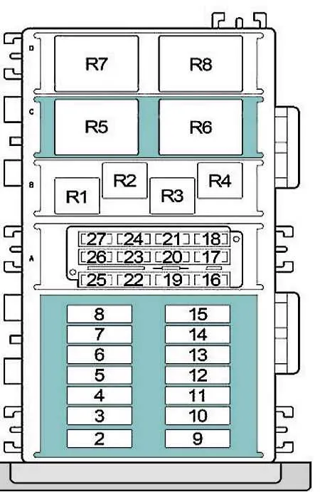
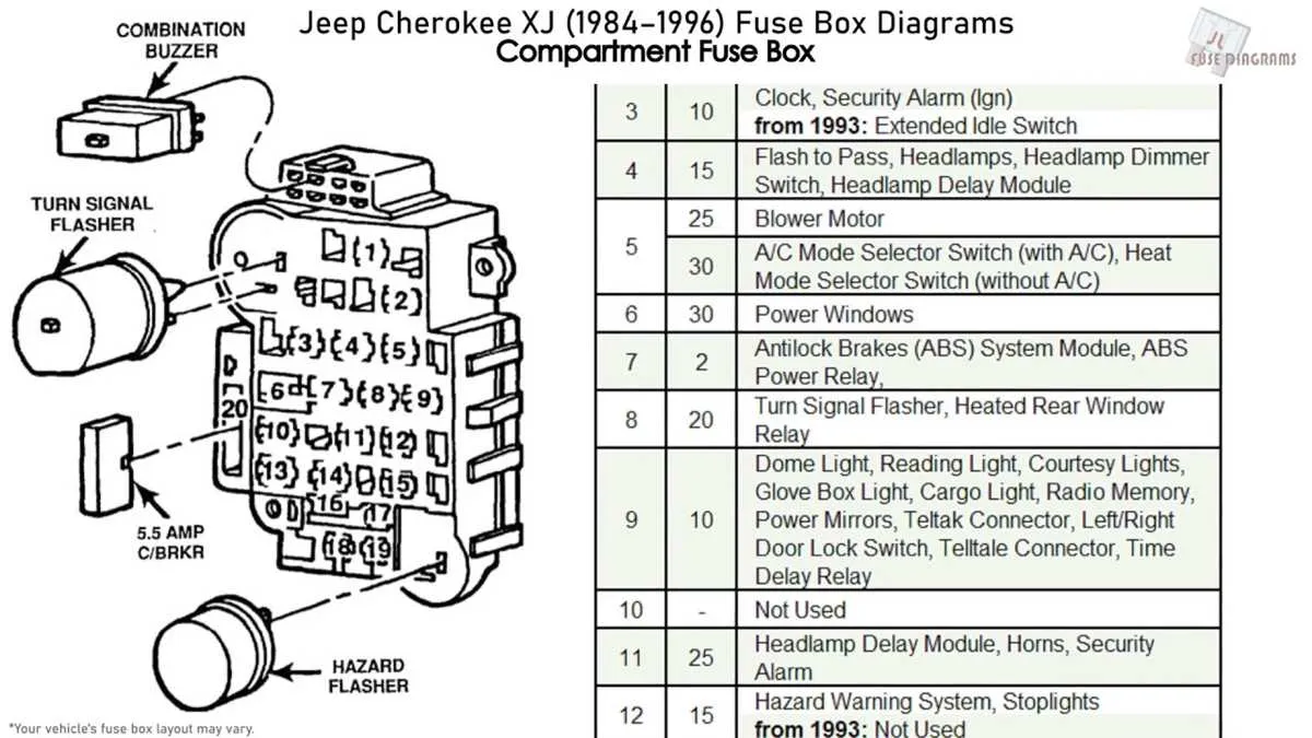
Locate the primary electrical panel beneath the dashboard on the driver’s side for quick access to circuits. Each fuse slot corresponds to a specific component, including headlights, ignition, fuel pump, and power windows.
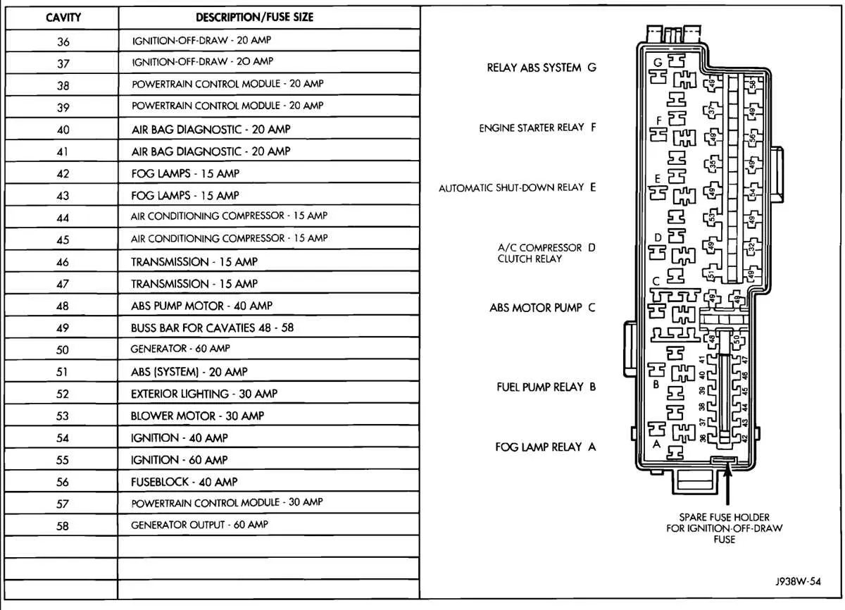
The main distribution center under the hood contains high-amperage fuses for the alternator, cooling fan, and radiator fan. Use a multimeter to test fuses if a component fails to operate, ensuring continuity.
Refer to the molded label on the fuse holder cover for precise amperage ratings and circuit assignments. Replace any blown fuses with the exact rating to prevent electrical damage or fire risk.
For lighting issues, check fuse positions labeled for dome lamps, tail lamps, and turn signals in the cabin compartment. Critical engine-related circuits are protected by fuses located in the engine bay panel.
When troubleshooting power accessories, confirm the integrity of fuses linked to the central locking system, power seats, and audio equipment. Always disconnect the battery before swapping fuses to avoid shorts.
Locating and Identifying Electrical Panel Components in the 2000 Jeep Cherokee

Start by accessing the main power distribution panel positioned beneath the dashboard on the driver’s side. Remove the protective cover by gently pulling on the latch near the steering column.
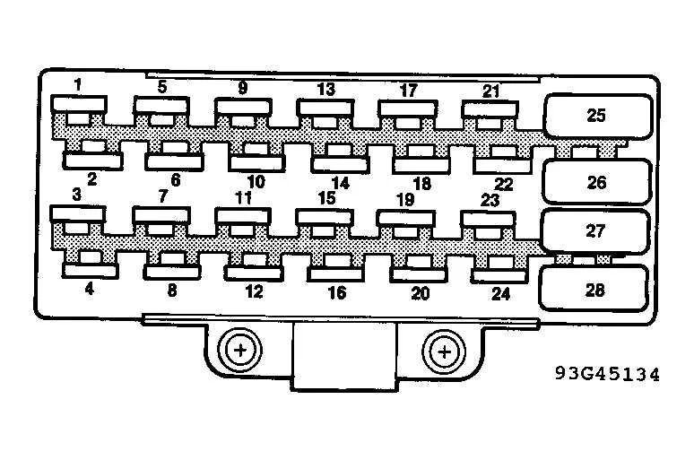
Inside, you will find a collection of relays and small cylindrical safety devices arranged in a molded plastic tray. Each element controls a specific circuit, such as lighting, ignition, or accessories.
The secondary control unit resides under the hood, near the battery on the driver’s side. This larger assembly contains higher amperage fuses and relays for critical systems including cooling fans and fuel injection.
Refer to the molded label inside the access panel for a detailed layout identifying each protective device by function and amperage rating. This eliminates guesswork and ensures correct component replacement.
Always disconnect the vehicle’s negative terminal before handling any of these electrical safeguards to prevent short circuits or damage to the circuitry.
Use a fuse puller or needle-nose pliers for safe extraction and inspection of the units, checking for any signs of damage or blown elements.
Step-by-Step Guide to Reading the 2000 Jeep Cherokee Fuse Box Diagram

Start by locating the power distribution panel under the dashboard or hood. Identify the layout label, usually printed on the cover or nearby, which maps each slot to its function.
- Check the legend to match each numbered fuse location with its assigned circuit, such as headlights, ignition, or radio.
- Use a test light or multimeter to verify if the fuse slot is energized before proceeding.
- Refer to amperage ratings indicated next to each fuse slot to ensure proper replacement values and avoid electrical issues.
- Inspect for any blown or damaged protective elements by visually checking for breaks in the wire filament inside each holder.
- Identify auxiliary relays often grouped near the fuses; these control high-current components and are vital for system operation.
- Trace wiring harness connections stemming from the panel to understand the flow of current to various subsystems.
- Consult the owner’s manual section dedicated to electrical layout for detailed circuit descriptions and troubleshooting tips.
Follow these steps methodically to accurately interpret the electrical control panel schematic and efficiently diagnose issues related to power distribution.
Troubleshooting Common Electrical Issues Using the Power Distribution Layout
Start by identifying the correct relay or circuit protector related to the malfunctioning component. Refer to the vehicle’s electrical panel schematic to locate the exact position of the relevant protector. Check for visible signs of damage such as burn marks or broken connectors.
Use a multimeter to measure continuity across the circuit protector terminals. A lack of continuity indicates a blown protector that requires replacement. Always replace with the exact amperage rating specified to prevent wiring damage.
Inspect adjacent relays and connectors for corrosion or looseness, as these often cause intermittent faults. Clean terminals with electrical contact cleaner and ensure firm seating.
| Issue | Location in Panel | Recommended Action | Typical Amperage |
|---|---|---|---|
| Non-functional headlights | Headlamp protector slot | Replace damaged protector; check relay operation | 15A |
| Radio no power | Accessory power protector | Test and replace if continuity fails; inspect wiring harness | 10A |
| Power windows not working | Window motor circuit relay | Swap relay with identical unit; test circuit protector for damage | 25A |
| Engine won’t start | Ignition circuit protector | Check for voltage; replace protector if open; verify relay click | 30A |
Regular inspection of all circuit protectors for discoloration or swelling can prevent unexpected electrical failures. Ensure the panel cover is securely fastened to protect internal components from moisture and debris.