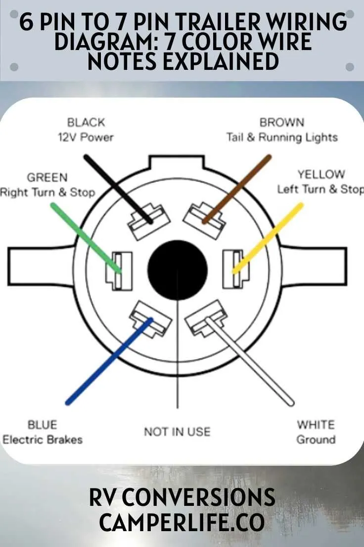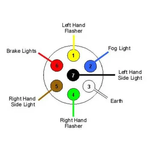
Use a standard 7-contact RV blade-style socket with flat terminals arranged in a circular pattern. The most common layout follows the SAE J2863 configuration. Always match the socket and plug types to avoid polarity errors or damage to electronics.
Terminal 1 (12 o’clock): Typically dedicated to the ground return path. Connect this directly to the vehicle chassis to ensure consistent electrical performance across all functions.
Terminal 2 (2 o’clock): Supplies auxiliary power (12V constant). Protect this line with a 40A fuse near the battery. This is often used to power internal lighting or charge an onboard battery.
Terminal 3 (4 o’clock): Activates electric brakes. Use 10-gauge wire for this line and connect it through a brake controller mounted in the towing vehicle.
Terminal 4 (6 o’clock): Controls tail and marker illumination. Use a 14-gauge conductor and tap into the vehicle’s tail light harness, ensuring isolation from turn signals.
Terminal 5 (8 o’clock): Sends the right turn indicator and brake signal. Route this from the right signal feed and confirm that dual-function signals are separated using a tail light converter if necessary.
Terminal 6 (10 o’clock): Sends the left turn indicator and brake signal. Wire identically to the right side, observing polarity and load limitations of LED vs incandescent systems.
Center terminal: Usually reserved for reverse lights. Connect this only if backup functionality is required and supported by the towed unit. Use a 16-gauge wire and confirm power is only active when reverse gear is engaged.
7-Way Connector Configuration
Use a standard 7-way RV-style socket with flat blade terminals arranged in a circular pattern. The top center terminal (often labeled as position 1) is typically for reverse signal or auxiliary power depending on the vehicle system. Verify with a multimeter before connecting.
Position 2 (bottom center) should carry ground. Connect this to the chassis frame using a corrosion-resistant ring terminal and secure with a self-tapping screw. Ensure clean metal contact to avoid voltage drop.
Position 3 (bottom left) delivers left turn and stop light signal. Use a 12-gauge wire for durability under repeated braking. Confirm voltage presence with lights active.
Position 4 (top left) provides brake controller output. This should run directly from the in-cab controller through a dedicated fuse. Minimum wire gauge: 10 AWG.
Position 5 (top right) handles right turn and stop lamp signal. It mirrors the left side but on a separate circuit. Match gauge to left side for symmetry.
Position 6 (bottom right) supplies tail and marker lights. This circuit should be protected with an inline 15A fuse and use weatherproof connectors at junction points.
Position 7 (center right) is for constant 12V supply, often powering interior lights or battery charging systems. Use a dedicated fused circuit from the vehicle’s battery with 10 AWG wire to prevent voltage sag under load.
Standard Color Code and Pin Functions in a 7-Way Connector

Follow this color scheme for consistent electrical connections across towing systems:
| Contact | Wire Color | Function |
|---|---|---|
| 1 (Center) | Yellow | Auxiliary / Reverse Lights |
| 2 | Green | Right Turn / Brake |
| 3 | Brown | Tail / Running Lamps |
| 4 | White | Ground Return |
| 5 | Blue | Electric Brakes |
| 6 | Red | Left Turn / Stop |
| 7 | Black | Battery Charge / 12V Power |
Use dielectric grease on terminals to prevent corrosion. Verify ground continuity before connecting any load. Match wire functions on both vehicle and towed unit ends to avoid malfunction.
How to Test Each Connector with a Multimeter Before Towing
Set the multimeter to DC voltage (20V range). Connect the black probe to a clean chassis ground. Use the red probe to check each socket on the towing vehicle’s plug, with ignition and lights on.
- Ground contact: Should read 0V against chassis. No continuity means corrosion or broken wire.
- Tail/marker lights: Turn on the vehicle’s lights. Voltage should be 12V. If absent, check the fuse and light switch.
- Left turn/brake: Activate the left signal. Expect 12V pulsing. No signal = faulty relay or bad socket.
- Right turn/brake: Repeat with the right signal. Same voltage and pulsing pattern.
- Electric brakes: Apply the manual override on the brake controller. Voltage should ramp up smoothly. Sudden drop = short circuit or loose contact.
- Reverse circuit (if used): Shift to reverse with engine running. Expect 12V on reverse contact.
- Auxiliary power: Check constant 12V feed (if wired). This powers interior lights or battery charging.
Repeat all steps with slight movement of the connector to detect intermittent faults. Clean and secure terminals showing unstable readings.
Connecting a 7-Terminal Plug for Brake Controller and Auxiliary Power
Match the brake control output wire to the blue terminal of the connector to ensure proper electric braking function. Use a dedicated wire gauge of 12 or 14 AWG to handle current demands safely.
For auxiliary 12V power supply, connect the circuit to the black terminal. This line must include an inline fuse rated between 10A and 20A, positioned near the power source to protect the system from overloads.
The ground wire should attach securely to the white terminal, establishing a reliable return path. Use a clean, unpainted metal surface for the connection to avoid electrical resistance and potential faults.
Signal lighting circuits require connections to brown (tail/running lights), yellow (left turn and brake), and green (right turn and brake) terminals. Employ weather-resistant connectors and color-coded cables to maintain clarity and durability.
Verify all crimps and solder joints for mechanical strength and electrical continuity. Utilize heat shrink tubing or dielectric grease on exposed contacts to prevent corrosion and ensure long-term operation.
Test the entire assembly with a multimeter and trailer light tester before installation to confirm each circuit responds correctly under load conditions from the brake controller and auxiliary power supply.