Ensure proper connection and configuration when wiring your system by closely following the manufacturer’s guide. Start by verifying that all power inputs and outputs are connected correctly to avoid potential malfunctions or inefficiency in operation. Check the power supply ratings, and ensure they match the unit’s requirements for a seamless installation.
Connections to the thermostat should be securely fastened, as these will directly influence the control of the system. Proper wiring ensures consistent temperature regulation and minimizes the risk of unexpected shutdowns. Make sure to use high-quality, insulated wires to prevent any safety hazards.
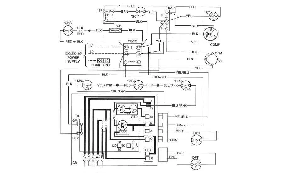
Pay special attention to the compressor wiring–this is the core element that regulates system functionality. A correct installation of the starting capacitor and connections to the motor can significantly enhance performance and energy efficiency. Double-check the continuity of all connections before turning on the system for the first time.
System Wiring Overview
To ensure proper operation of the thermal regulation system, precise wiring is critical. First, confirm that the power supply lines are correctly connected to the primary control unit, ensuring a steady flow of current to the internal components. Each circuit should be clearly marked and segmented to avoid any misconfigurations during installation or maintenance.
Next, focus on the integration of the compressor and the reversing valve. These components should be connected to dedicated relays to control the switching mechanism efficiently. Use wires rated for the appropriate current to avoid overheating, especially when handling high-power units.
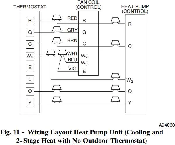
For user interface integration, ensure that the thermostat connections are made using shielded cables to minimize interference. The control signals between the temperature sensors and the main processor need to be routed with care, maintaining signal integrity over long distances.
Proper grounding is essential for safety. Make sure that the system is grounded through an earth terminal to prevent any electrical hazards. A robust grounding connection not only safeguards against electric shocks but also ensures the overall longevity of the system by reducing electrical wear.
Understanding Power Supply Connections for Heat Pumps

To ensure efficient operation, proper power supply connections are essential. Begin by checking the voltage requirements for the system, typically ranging from 220V to 480V, depending on the model. Incorrect voltage can cause malfunctions or permanent damage.
Follow these steps for correct wiring:
- Ensure the power source matches the required voltage and phase (single-phase or three-phase).
- Use dedicated circuits with appropriate fuse protection to safeguard against overloads.
- Verify ground connections to prevent electrical hazards.
Use cables rated for high current to avoid overheating. Always check the wiring standards in your region to comply with safety regulations. For reliable performance, use high-quality components such as copper wire and corrosion-resistant terminals.
- Do not overload circuits by connecting additional devices.
- Confirm the integrity of the power supply using a multimeter before final installation.
Installation should only be performed by certified professionals to meet local code requirements and prevent risks associated with improper setup.
Wiring and Component Layout in Heat Pump Systems

Ensure proper isolation of each component to prevent interference and ensure reliable operation. Start by positioning the primary unit, ensuring that the connection points for the power supply and internal circuit are accessible. This will facilitate maintenance and troubleshooting without having to dismantle the system. Be sure that the main board is mounted securely with minimal exposure to external factors that could cause wear or damage.
Efficient cable routing is critical to avoid overheating or signal loss. Keep the wires short and direct, avoiding unnecessary bends or loops that could increase resistance or interfere with the system’s performance. Use cable trays or clips to secure wiring away from moving parts or sources of heat. Always use cables rated for the specific voltage and current requirements of each component.
Component groupings should follow a logical sequence based on function. For example, control units should be grouped together for easier access and troubleshooting, while thermostats and sensors must be strategically placed to ensure accurate readings. Avoid placing high-power components too close to sensitive electronics, as this can cause interference or damage.
Label all wires and terminals clearly to simplify future maintenance. Use standardized color codes and consistent labeling for easy identification. This will reduce the time spent on repairs and help anyone working on the system to quickly understand the setup.
Troubleshooting Common Issues in System Wiring
Check the power supply first. Ensure the breaker is switched on and the fuse is intact. A blown fuse can disrupt current flow, preventing the unit from functioning. If the circuit is fine, inspect the voltage across input terminals–low voltage might indicate a malfunction in the source or improper connection.
If the device isn’t starting, verify the control board for visible damage, such as burnt components or disconnected wires. A faulty control board can prevent the unit from powering up or responding to commands. Ensure all wiring is securely attached, with no signs of wear or corrosion that might interrupt signals.
In case of erratic behavior, examine the relay connections. If any of the relays are stuck or malfunctioning, they may cause the unit to operate incorrectly or intermittently. Consider testing the relay with a multimeter for continuity.
Another issue can arise with sensors. If the system shows inconsistent performance or errors in temperature regulation, the sensors might be faulty or miscalibrated. Test sensor resistance and replace if needed to ensure accurate readings and reliable operation.
Lastly, inspect the capacitor. If it appears swollen or damaged, it may no longer be able to store the required charge, leading to power issues. Replacing a malfunctioning capacitor can resolve many starting and running problems.