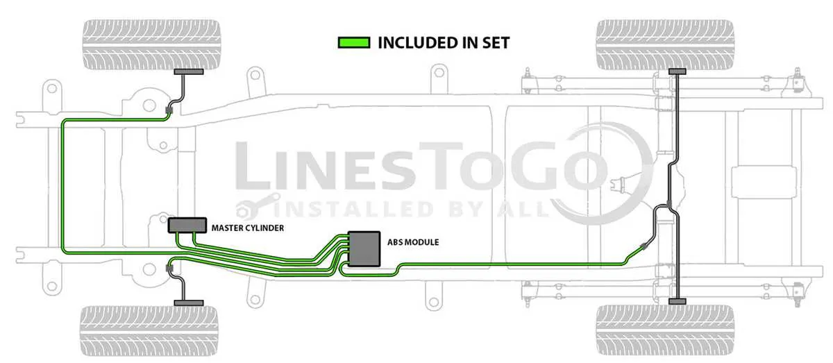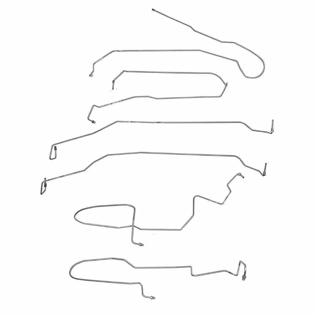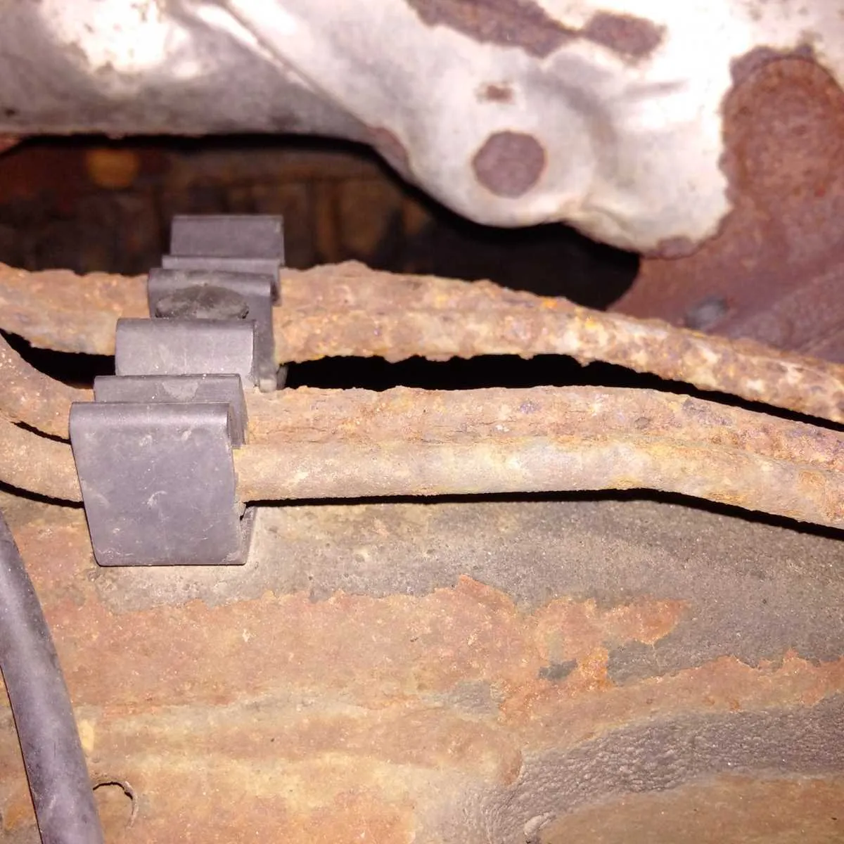
Begin by inspecting the primary conduit running from the master cylinder to the ABS module. This pathway typically follows the driver-side frame rail and is secured by metal clips every 12 to 18 inches. Any signs of corrosion or abrasion along this section should prompt immediate replacement with stainless-steel tubing for durability.
Next, trace the distribution block located near the midsection, which channels fluid to the rear assemblies. It often branches out just past the cab, splitting into dual conduits extending to each rear wheel. These are routed above the fuel tank and are prone to rust due to trapped moisture–consider rerouting slightly lower for easier access and inspection.
For the front channels, observe how the flex hose transitions at the wheel wells. Each side receives fluid through a rigid-to-flex junction mounted on the upper control arms. Use a double flare fitting here to prevent leaks under high pressure. Ensure that the routing avoids contact with suspension components throughout the steering arc.
To finalize, confirm that all mounting tabs, grommets, and junction points are intact. Any looseness can result in vibration wear. A pressure bleed test after installation ensures no air remains in the system, preserving pedal response and overall performance.
Detailed Routing Map for Hydraulic Tubing System

Start by inspecting the master cylinder area where dual conduits exit toward the ABS module, located on the driver-side frame rail. From there:
- Front wheel channels split near the module–left side routes directly forward, right side crosses under the radiator support.
- Rear distribution runs rearward along the inside of the driver-side frame, secured with factory clips spaced approximately 12 inches apart.
- Near the rear axle, a flexible coupling connects the solid tube to a rubber hose that feeds into a rear T-junction block mounted on the differential housing.
- Individual rear conduits exit the block and extend to each wheel cylinder, routed above the axle and clipped to avoid contact with moving suspension parts.
Use 3/16″ steel-coated tubing for replacements. Ensure all bends match OEM curvature to maintain clearance and prevent stress fractures. Thread fittings are standard inverted flare–verify compatibility before installation.
Location and Routing of Brake Lines on the 2004 Silverado Frame

Begin inspection at the master cylinder, where the hydraulic tubes exit toward the driver’s side frame rail. The primary conduit follows the inner edge of the left frame channel, secured with steel clips approximately every 18 inches.
Near the transmission crossmember, the rear distribution pathway branches off, crossing above the driveshaft tunnel via a protective bracket before descending along the passenger-side frame rail toward the rear axle.
At the rear, a flexible hose connects the solid tubing to the axle-mounted splitter block. From there, dual rigid extensions run laterally to each wheel hub, hugging the axle contour and anchored with U-clamps to prevent vibration fatigue.
Front circuits split from a junction block mounted beneath the steering gear. Each path routes forward, curving behind the suspension arms, and terminates at flexible hoses bolted to the caliper brackets. Ensure grommets are intact where tubing passes through support brackets to prevent chafing.
Identifying Connection Points to Master Cylinder and ABS Module

Start by locating the hydraulic control unit mounted near the driver-side frame rail. Trace the pair of metal tubes extending from the proportioning valve; these lead directly to the primary and secondary ports on the reservoir assembly. The upper port typically routes fluid to the rear circuit, while the lower one feeds the front distribution system.
Next, find the anti-lock controller positioned beneath the frame, close to the driver’s side. It has multiple fittings–usually six–that manage input from the reservoir and distribute pressure to each wheel. The two inlet ports are the larger connections coming from the master assembly. Confirm routing by referencing the line diameters: input channels are thicker, while the outputs to the calipers are thinner and branch outward to each corner.
Check for threaded unions at each junction, and inspect for corrosion or leakage. Use a line wrench to avoid rounding off soft steel fittings when verifying connections. Each tube should follow a secured path with factory clips–any deviation may indicate a previous repair or misrouting.
Differences Between Front and Rear Hydraulic Tube Configurations
Front tubing employs a more complex routing due to the presence of steering components and suspension travel. It typically includes flexible hoses near the wheels to accommodate movement, while the rigid metal conduit runs along the frame. This setup requires corrosion-resistant materials and secure mounting brackets to prevent damage from road debris and vibration.
Rear conduit features a simpler, straighter path with fewer bends, as the rear axle assembly is less dynamic compared to the front suspension. The tubing is generally longer and fixed firmly along the chassis, often integrating fewer flexible segments. It is essential to check for rust-prone areas where the tubes pass through body mounts or crossmembers.
Key recommendations: When inspecting the fluid transfer system, prioritize flexible hose integrity on the front assembly due to its exposure to movement and wear. For the rear, focus on the metal tubing’s corrosion resistance and secure fastenings. Replacement parts should match original specifications, considering diameter, material thickness, and fitting types to maintain system reliability and safety.