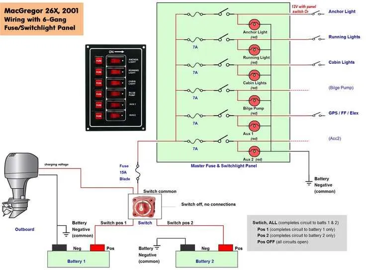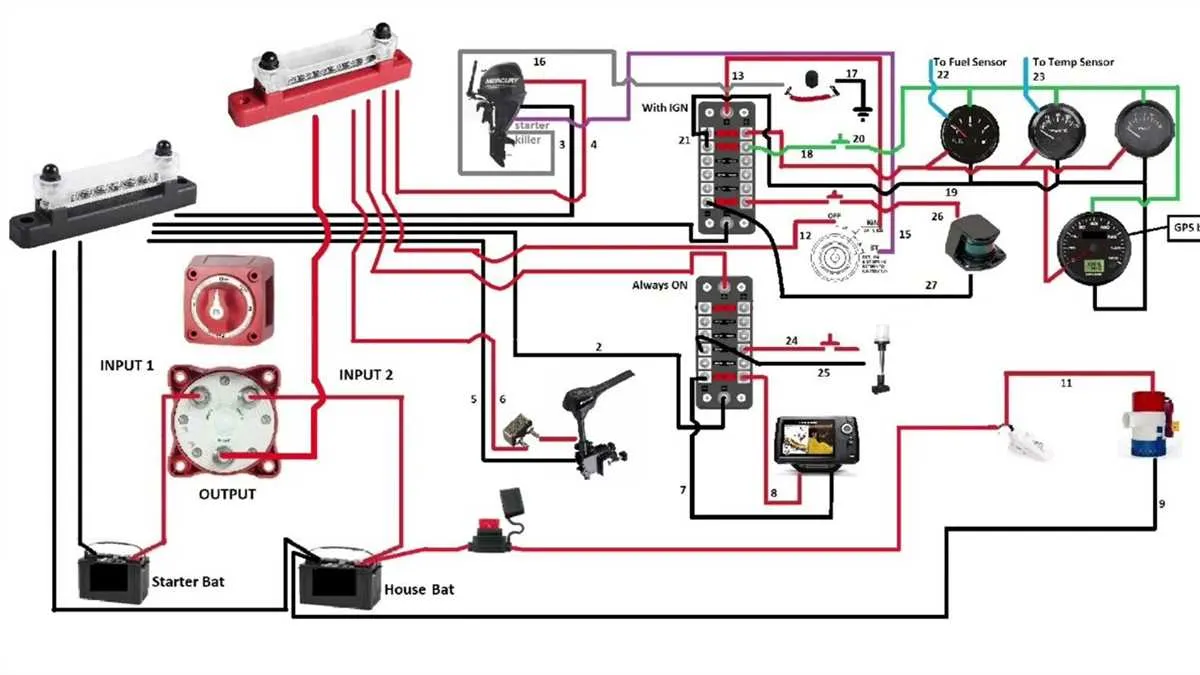
Start by mapping the power sources: clearly mark the battery banks, shore power connections, and alternators. Use heavy-gauge cables (at least 4 AWG) for main feeds to minimize voltage drops and ensure safety. Protect all lines with appropriately rated circuit breakers or fuses close to the power source.
Label each circuit precisely to avoid confusion during installation and troubleshooting. Separate systems such as navigation, lighting, bilge pumps, and entertainment should have dedicated lines and protective devices. Use marine-grade wiring and connectors rated for saltwater exposure to prevent corrosion and maintain reliability.
Follow a logical flow from the main distribution panel to individual components. Incorporate color-coded cables–red for positive, black for negative, and green for grounding–to maintain consistency. Ensure all grounding points connect to a common bus bar to reduce electrical noise and enhance system stability.
Electrical Layout Guide for Marine Vessels
Always use marine-grade cables and connectors rated for saltwater exposure to prevent corrosion and ensure safety. Follow these key steps when creating the electrical plan:
- Identify all power sources, including batteries, alternators, and shore power connections.
- Map out circuits separately: lighting, navigation, bilge pumps, electronics, and accessories.
- Use circuit breakers or fuses for each branch to protect wiring and devices from overload.
- Implement color-coded insulation for easy identification of positive, negative, and ground wires.
- Keep cable runs as short and direct as possible to minimize voltage drop.
- Install a common grounding bus connected securely to the hull to avoid electrical faults.
- Label all terminals and connections clearly to facilitate troubleshooting and maintenance.
Remember to verify all connections with a multimeter before powering up. Ensure compliance with relevant marine electrical standards such as ABYC or IEC guidelines.
How to Plan and Label Your Marine Electrical System

Start by mapping all power sources and electrical loads, grouping circuits by function–navigation, lighting, bilge pumps, and accessories. Assign a unique identifier to each line, using durable, waterproof labels with clear, concise codes to avoid confusion during maintenance.
Choose cable sizes based on the maximum expected current, applying marine-grade standards to prevent voltage drop and overheating. Document circuit breaker ratings and fuse types alongside each connection point for quick reference.
Position distribution panels in accessible, dry locations. Create a color-coded key matching cable insulation to specific circuits, such as red for positive, black for negative, and yellow or blue for auxiliary systems.
Maintain a detailed schematic reflecting the exact routing and termination points of all conductors. Include grounding paths and bonding details to ensure safety and reduce electromagnetic interference.
Update the system map every time modifications occur. Store both digital and printed copies onboard to aid troubleshooting and future upgrades without guesswork.
Choosing and Connecting Marine-Grade Wiring and Components
Always use tinned copper cables with marine-grade insulation. These materials offer superior resistance to corrosion caused by saltwater exposure. Choose cables with a high strand count to ensure flexibility and durability under harsh conditions. Opt for a 16 AWG to 10 AWG wire gauge, depending on the power needs of your devices. Use UL 1426-rated cable for optimal resistance to UV rays and saltwater.
When selecting terminals and connectors, prioritize those rated for marine use. Stainless steel or nickel-plated options prevent rust and degradation. Crimp connectors should be tightly fitted and, if possible, heat-shrink, to prevent moisture infiltration. Always use waterproof connectors with rubber seals to minimize exposure to water.
For any junction boxes or distribution panels, ensure they are sealed and watertight. Mount these components in accessible areas with proper strain relief to avoid wear on connections. Additionally, use circuit breakers designed for marine applications to protect the system from short circuits and overloads.
When installing fuses, ensure they are rated slightly higher than the expected load to prevent unnecessary tripping. Choose fuse blocks with corrosion-resistant covers, especially in areas where exposure to water is inevitable.
Grounding should be done using a dedicated bus bar, and the grounding system must be connected to the hull in a way that avoids electrolysis. Always check connections for tightness to prevent any potential electrical issues in the future.
Troubleshooting Common Electrical Issues on Watercraft
Inspect all connections and terminals for signs of corrosion. Corroded or loose connectors are a frequent cause of malfunction. Ensure all terminals are clean and tightly secured to prevent power loss.
Check the fuse box for blown fuses, which can lead to complete system failure. If a fuse keeps blowing, it may indicate an underlying short circuit or faulty component. Replace the fuse with one of the correct amperage.
Measure voltage levels at key electrical components. A low voltage reading indicates problems in the power supply, such as a weak battery or faulty alternator. Replacing or recharging the battery often solves this issue.
Verify the grounding system. Poor ground connections often result in erratic performance of electronics. Use a multimeter to test ground continuity and make sure all ground wires are properly connected.
Examine switches and relays for signs of wear or failure. Test their functionality with a multimeter and replace any malfunctioning components to restore proper operation.
Inspect the electrical panel for any burnt wires or damaged insulation. Such issues can cause overheating or even fires if left unresolved. Replace any damaged cables immediately.