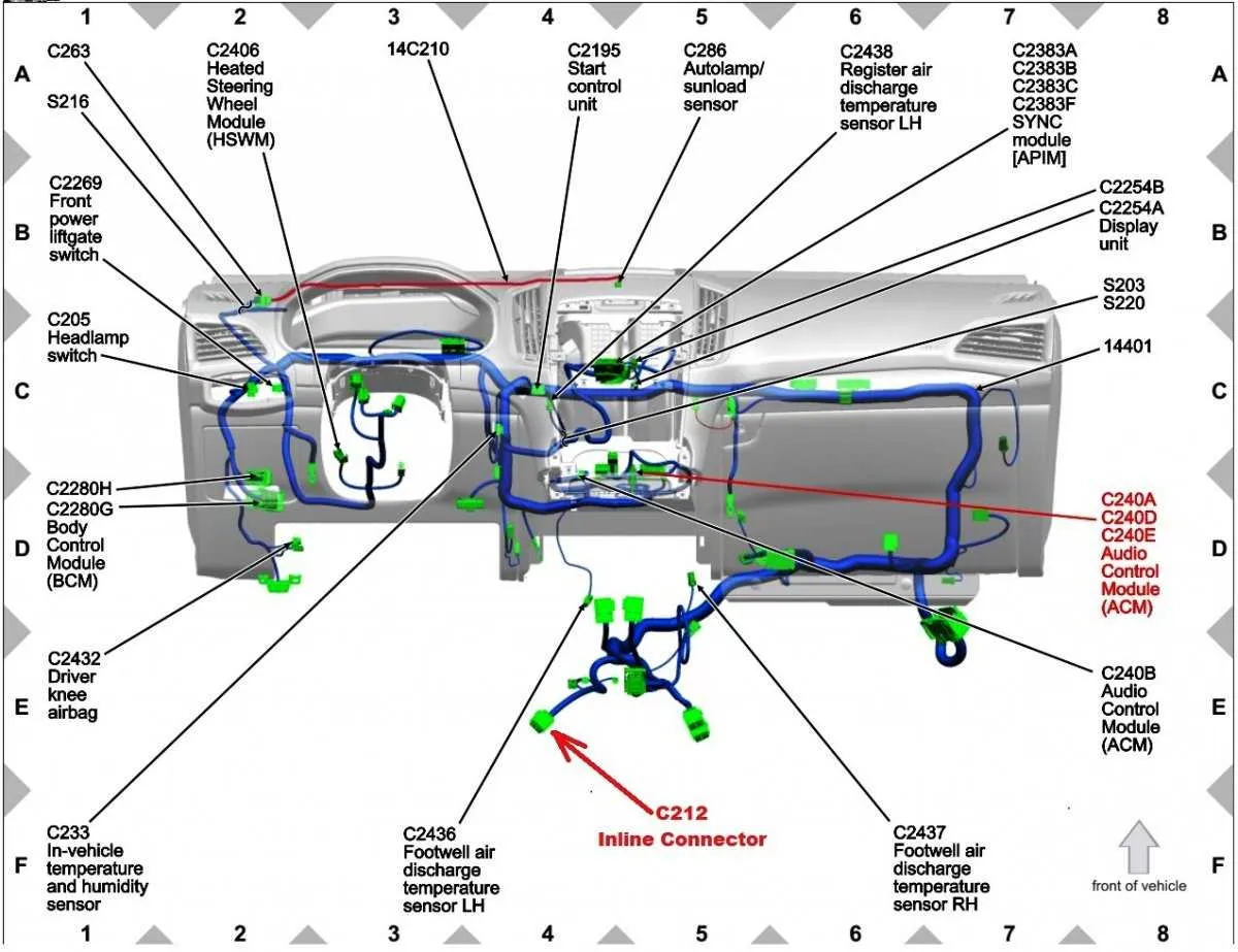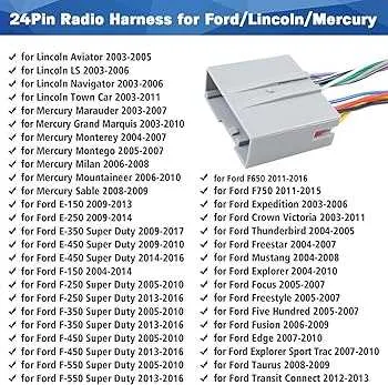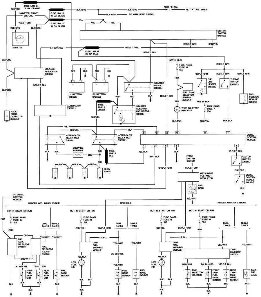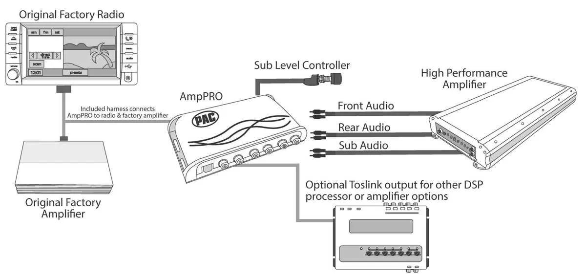
For a reliable installation of your vehicle’s sound unit, match each color-coded wire precisely to its corresponding terminal. The power feed typically runs through a red cable, while the ground connection is linked via a black or brown line. Ignoring proper polarity may cause system malfunctions or permanent damage.
Use a pinout reference tailored specifically for your model year to ensure compatibility. Variations in connector layouts and wire functions are common between different production runs, so a generic guide often leads to errors.
Confirm voltage levels before connecting the accessory wires, especially those responsible for illumination and antenna control, to avoid shorts or blown fuses. Employ a multimeter for precise measurement during the process.
Electrical Connector Layout for Vehicle Audio System
For proper integration of the audio unit in the pickup truck, match the color-coded cables with the factory terminal blocks precisely. The power feed typically uses a red wire for ignition-switched 12V and a yellow wire for constant battery voltage. Ground connections are black and must be securely attached to the chassis to avoid noise interference.
Speaker leads are grouped by pairs: front left usually white and white with black stripe, front right gray and gray with black stripe, rear left green and green with black stripe, rear right purple and purple with black stripe. Confirm polarity to prevent phase cancellation and sound distortion.
Remote turn-on lead, often blue, activates external amplifiers and should connect directly to the amplifier trigger input. Antenna power feed wire, also blue but sometimes striped, supplies voltage to the power antenna or amplifier, so verify before splicing.
When replacing the original interface, ensure the aftermarket adapter matches pin assignments exactly, or use a multimeter to trace signals. Incorrect connections may cause malfunction or damage to the audio control unit.
Always disconnect the battery before handling connectors to prevent shorts or electrical shocks. After installation, test all functions: power on/off, speaker output on all channels, and auxiliary features to confirm correct hookup.
Identifying Pin Functions and Wire Colors in Vehicle Audio Connector

To correctly map each terminal, focus on the standardized color coding and pin assignments used in the factory connector.
- Yellow: Constant 12V power (battery feed)
- Red: Switched 12V ignition power (accessory feed)
- Black: Ground connection (chassis earth)
- Blue: Power antenna or amplifier turn-on signal
- White and White with Black stripe: Front left speaker positive and negative respectively
- Gray and Gray with Black stripe: Front right speaker positive and negative respectively
- Green and Green with Black stripe: Rear left speaker positive and negative respectively
- Purple and Purple with Black stripe: Rear right speaker positive and negative respectively
Each pin location is fixed, with power pins generally clustered together and speaker wires positioned symmetrically for left and right channels. Always verify voltage presence with a multimeter before final connections.
- Locate the constant power wire (usually yellow) to ensure memory functions remain active.
- Check the accessory feed (red) that powers the unit only when ignition is on.
- Identify and separate speaker pairs by color and polarity for correct stereo output.
- Confirm ground wire continuity to prevent electrical noise or interference.
- Test the blue wire function if using a power antenna or external amplifier trigger.
Proper identification prevents damage and ensures optimal sound performance from the installed unit.
Step-by-Step Guide to Connecting Aftermarket Audio Systems Using OEM Connector

Begin by disconnecting the vehicle’s battery to avoid short circuits. Locate the factory plug behind the dashboard where the original sound system was installed. Identify the color-coded leads on the connector: typically, red for ignition power, yellow for constant power, black for ground, and pairs of white, gray, green, and purple for speaker outputs.
Match these wires to the aftermarket unit’s input harness using a multimeter or wire chart specific to the truck model. Use crimp connectors or solder joints covered with heat shrink tubing for secure, corrosion-resistant connections. Ensure the speaker wires correspond correctly: white and white/black for front left, gray and gray/black for front right, green and green/black for rear left, purple and purple/black for rear right channels.
Connect the power leads carefully–constant 12V to the yellow wire to preserve memory functions, switched 12V to the red wire for operation when the ignition is on, and ground wire to the black lead for stable electrical reference. Test each connection with a voltmeter before plugging the adapter into the vehicle’s connector.
Once all connections are verified, secure the aftermarket unit in the dashboard and reconnect the battery. Power on the system to confirm proper function: check audio output on all channels and verify retention of presets or clock settings. Adjust wiring if any channels are muted or reversed.
For integration with steering wheel controls or external amplifiers, consult specific interface modules compatible with the truck’s native connector. Avoid cutting original vehicle wires beyond the factory plug to maintain resale value and ease future repairs.
Troubleshooting Common Electrical Connection Issues with Vehicle Audio Systems

Start by verifying continuity on the main power and ground lines using a multimeter to exclude breaks or shorts. Pay special attention to the connector pins for corrosion or bent terminals that often cause intermittent power loss or signal failure.
Check the ignition-switched power source; if the stereo does not turn on with the key, confirm voltage presence at the accessory wire. Absence here usually indicates a blown fuse or a faulty relay in the fuse box.
Inspect speaker leads for correct polarity and secure contact. Reversed polarity or loose terminals generate distortion or no sound output. Use a tone generator to trace speaker wires if needed.
Grounding issues are frequent causes of audio dropouts and static noise. Ensure the chassis ground wire is tightly fastened to a clean, bare metal surface, free of paint or rust.
When adding aftermarket components, verify compatibility of pin assignments to prevent damage. Cross-reference pin functions with the vehicle’s electrical manual rather than assuming universal standards.
Finally, look for damaged insulation or crushed cables inside the door panels and firewall passageways. Mechanical stress often leads to short circuits or open connections over time.