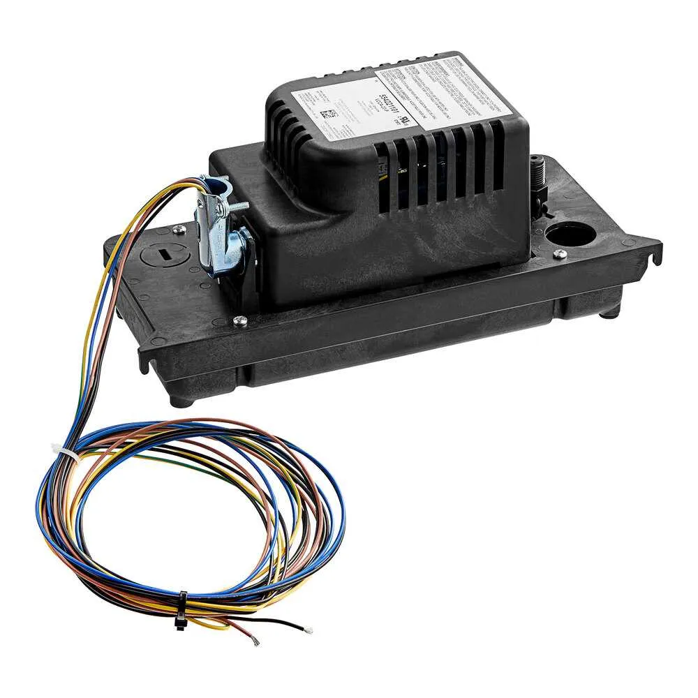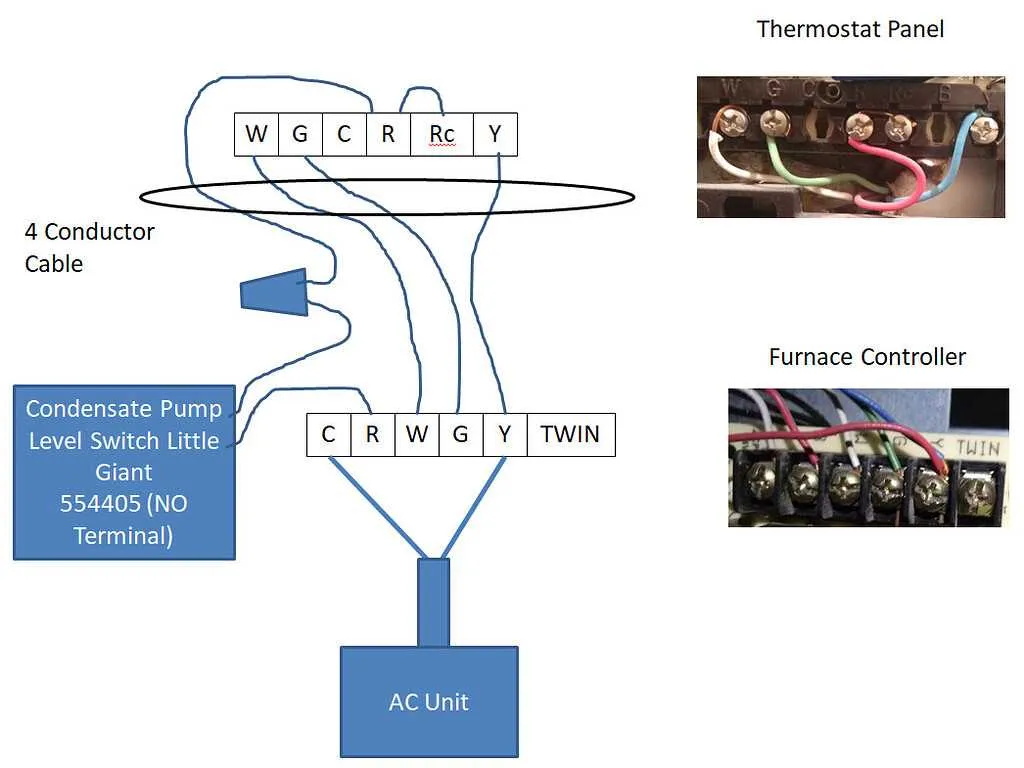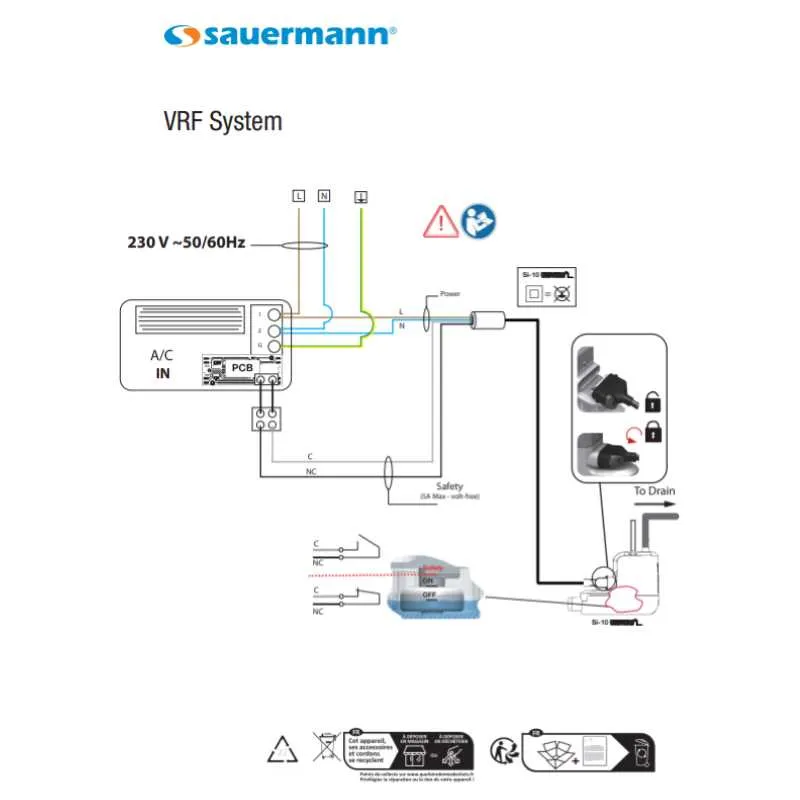
To ensure your drainage system functions efficiently, understanding the correct electrical setup is crucial. Begin by connecting the appropriate terminals to the correct power source. Always verify that your circuit is rated to handle the specific voltage and current requirements of your system to prevent any electrical failures.
When assembling the electrical components, prioritize the use of high-quality connectors and insulated wiring. This will enhance the longevity and reliability of your installation. Ensure that all connections are tight and properly insulated to avoid any short circuits or power loss.
For those installing a control switch or relay, make sure that the device is positioned in a location where it can be easily accessed for maintenance but remains protected from environmental factors. A double-pole switch is often recommended for ensuring a safe and secure connection.
To maintain operational efficiency, regularly inspect the connections for signs of wear or corrosion, especially in areas exposed to moisture. Replacing damaged wires or connectors promptly will prevent potential malfunctions and ensure smooth operation.
Electrical Connections for Drainage Systems
For an efficient setup, ensure proper connection of the water removal system to the electrical circuit. Begin by linking the device to a dedicated circuit with an appropriate breaker to avoid overloads. Use a grounding wire to prevent electrical faults that could damage the components.
When connecting to the power source, double-check that the voltage and current ratings match the device’s specifications. For most models, a 120V AC connection is standard, but always verify before installation. Use three-prong plugs for safety, ensuring proper grounding.
Ensure the activation switch is in place to allow the system to start automatically when moisture reaches a specific level. A float switch or pressure sensor will typically control this, but make sure it’s properly wired to the relay to ensure accurate operation.
The control panel should be linked to the main system and wired to both the power source and the float mechanism. Additionally, check the wiring connections for wear and tear, especially at high-stress points like the connector terminals and floating components.
Tip: Use high-quality insulated wires to prevent short circuits. Keep the connections tight and secure to avoid issues with electrical flow. Always refer to the manufacturer’s manual for specific wiring requirements tailored to your device model.
For long-term reliability, consider placing the system in an environment free from excess moisture and heat. This will ensure the electrical components remain functional and free from corrosion over time.
How to Wire a Drainage System with Basic Components

Start by connecting the power supply to the main terminal block of the unit. Use a 120V or 240V AC source, depending on the unit specifications. Make sure the electrical circuit is turned off before proceeding with any connections.
Next, connect the ground wire to the grounding terminal to ensure safety. This is critical to avoid electric shock or short circuits. For the neutral wire, connect it to the neutral terminal of the control panel or switchboard.
For the pump’s activation mechanism, link the relay or switch to the control system. When the liquid reaches a specific level, the sensor will trigger the relay, starting the motor. Ensure the relay is rated for the motor’s amperage.
Wire the motor leads to the terminals on the relay. One wire should go to the common terminal, while the other connects to the normally open terminal of the relay. Verify the motor voltage is compatible with the incoming supply voltage.
For fluid level sensing, connect the float switch to the control system, ensuring the wiring is secure and protected from exposure to moisture. This will enable automatic activation when the liquid reaches a certain height.
Finally, double-check all connections for correct polarity and secure fastening. Power up the system to test functionality. Adjust the float switch position if necessary to ensure optimal fluid management.
Common Electrical Issues and Troubleshooting Tips

Ensure all connections are tightly secured to prevent intermittent power loss. Loose terminals can result in erratic performance or complete failure to activate. Regularly inspect the terminals for corrosion, especially in high-moisture environments, as this can cause poor conductivity.
When the device fails to turn on, check the fuse or circuit breaker. A blown fuse or tripped breaker can disrupt the entire system. Reset the breaker or replace the fuse if necessary, but confirm the cause of the issue to avoid repeated failures.
If you hear a humming noise without operation, this typically points to a jammed motor or an issue with the impeller. Inspect for any debris or obstructions blocking the rotor’s movement. If the rotor turns freely but the sound persists, the motor may be faulty and require replacement.
Incorrect voltage can cause underperformance or damage. Use a multimeter to verify that the system is receiving the appropriate voltage as specified in the product’s manual. A mismatch in voltage might indicate a problem with the electrical supply or a fault in the internal components.
Improper grounding can lead to electric shock hazards or malfunctioning of internal components. Confirm the ground connection is solid, and there’s no sign of wear or damage to the grounding wire.
Inconsistent operation might also be caused by a faulty float switch. If the float doesn’t trigger the system correctly, inspect its mechanism for debris or damage. If the float is stuck or worn out, replace it to restore functionality.
Overheating of components can occur due to insufficient ventilation. Ensure that the system has adequate space for airflow around it. Blocked vents or dust accumulation can cause thermal shutdown or permanent damage to sensitive parts.
If all checks are in order, but the system continues to malfunction, consider verifying the internal circuitry. Traces or solder joints can crack or degrade over time. Reflowing solder or replacing damaged circuit boards might be necessary.
Step-by-Step Guide to Connecting a Drainage Unit for HVAC Systems
Follow these detailed steps to ensure a secure and efficient installation of your drainage unit for HVAC systems:
- Begin by selecting a suitable location near your system’s drain outlet for the unit.
- Ensure the chosen area has a stable surface to mount the unit securely. Check for enough clearance around the unit for airflow and maintenance access.
- Turn off the power supply to the HVAC system and disconnect any existing electrical connections to avoid any electrical hazards during installation.
- Locate the wiring terminals on the device. These are typically labeled for easy identification.
- Connect the live (hot) wire from the power source to the designated terminal on the unit. This wire should be secured with a clamp or screw to prevent accidental disconnection.
- Attach the neutral wire to the corresponding terminal. This wire completes the circuit for proper functioning.
- If there is a ground wire, connect it to the grounding terminal to ensure safety. Make sure the connection is tight and secure to prevent any electrical faults.
- Once the connections are made, check them for tightness using a screwdriver or torque wrench to avoid loose contacts.
- Ensure the power supply is routed correctly and safely to avoid damage from overheating or exposure to the elements.
- After completing the electrical connections, secure all wires in place using cable ties or clips. This prevents wires from becoming loose or damaged over time.
- Double-check the entire system for any exposed wires or improper connections before reactivating the power supply.
- Test the unit by restoring power and monitoring its operation. Ensure the system responds to changes in water levels and activates as expected.
By following these instructions, you will guarantee that your drainage unit operates efficiently and safely within your HVAC system.