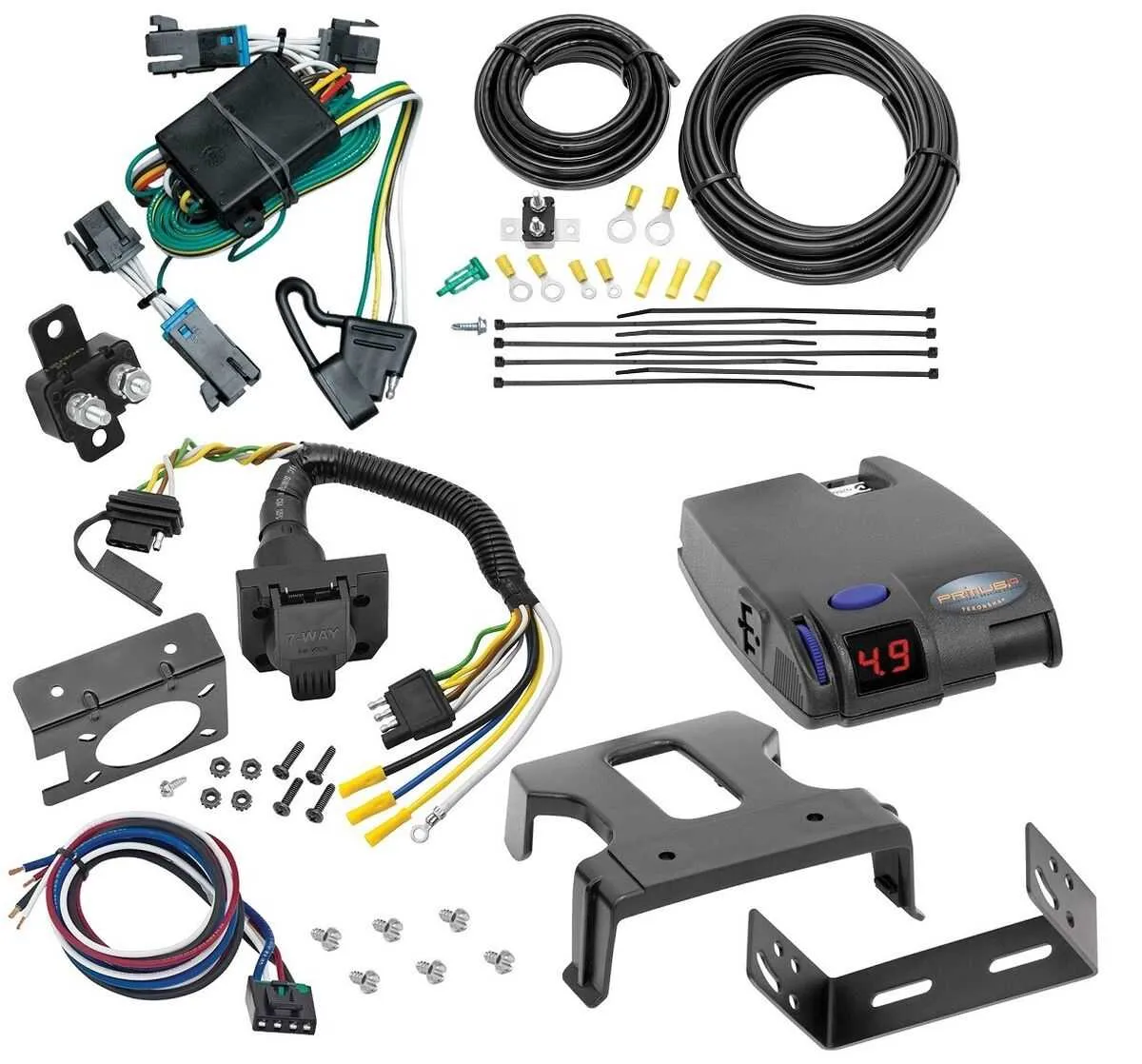
Start by ensuring proper identification of each cable within the vehicle’s electrical system. Correctly locating the input and output terminals is crucial for safe operation. Follow the manufacturer’s instructions carefully to connect the power source to the device, making sure to ground the system properly. A solid ground connection ensures stability and prevents electrical interference.
Next, secure the linkage between the towing vehicle’s electric circuitry and the braking mechanism on the attached load. For reliable performance, use the designated cables that are resistant to wear and weather conditions. Proper insulation is essential to avoid accidental short circuits or disconnections. Do not attempt to bypass factory recommendations, as they guarantee optimal performance and safety.
Once the electrical lines are set up, perform a thorough inspection of all connections. Tighten the terminals and check for any frayed wires or loose components. Testing the connection before full use is essential to prevent unexpected malfunctions. Ensure that all cables are appropriately secured, and that no part of the wiring is exposed to potential damage from friction or environmental factors.
Finally, perform a trial run to verify that the system operates as intended. The system should respond promptly and effectively to the braking signals, with no delay or malfunction. If you experience any issues, refer to the troubleshooting guide to correct wiring errors or device malfunctions. Regular maintenance checks will also help to extend the life of the system and ensure continued safe operation.
Electrical Connections and Setup

Ensure you identify the correct terminal on your device before proceeding with installation. Begin by connecting the power source to the designated input terminal. Next, wire the output to the vehicle’s electric braking system, ensuring proper insulation to avoid short circuits. Connect the ground wire securely to the chassis to complete the electrical circuit.
The third terminal typically requires linking to the brake light signal, allowing the system to activate automatically when the vehicle’s brakes are engaged. Be sure to connect the emergency breakaway switch to the system’s designated terminal, ensuring immediate response in the event of detachment.
Check each connection for stability and verify that the wires are routed away from any moving parts or sources of heat to prevent wear over time. Tighten all screws and inspect for any loose connections before testing the system.
Understanding the Power Connections
To ensure proper functionality, connect the power input wire directly to the vehicle’s battery. This should be done using a dedicated 12V circuit, ideally fused with a 30A fuse. A reliable ground connection is critical; use a solid chassis grounding point or the vehicle’s negative terminal to minimize interference and voltage drops.
The device requires a steady 12V source, so ensure that the circuit is not shared with other high-power devices. Check the wire gauge to handle the current load; 10 or 12 AWG wires are usually sufficient for this purpose. Improper connections or insufficient wire size can lead to malfunctioning or even damage to the unit.
If the power source is located far from the device, consider installing a relay to ensure smooth voltage delivery. This will prevent excessive voltage drop over long distances, which can affect performance. Always verify the power circuit is protected with a fuse at both the power input and any intermediary connection points.
How to Properly Wire the Brake Signals
Start by connecting the power supply directly to the system’s power terminal, ensuring it’s securely fastened. Then, run a wire from the unit’s output terminal to the vehicle’s electrical system. The wire should be durable and capable of withstanding the heat and vibrations encountered during travel. Ensure proper insulation to avoid short circuits.
The next step is to connect the signal wire to the actuator. This ensures that the system receives the correct input when braking forces are applied. It’s essential to use a high-quality, corrosion-resistant connector for this connection to ensure long-term reliability.
Once connected, test the setup by applying the brakes. If the signal is not being transmitted correctly, double-check all connections and ensure there’s no loose wiring. For vehicles with a digital readout, monitor the performance to ensure smooth operation.
Finally, secure all wires to prevent movement that could cause wear or disconnections. Use zip ties or other suitable fasteners to keep the cables in place. Avoid placing the wires near heat sources or sharp edges that could cause damage over time.
Grounding and Safety Considerations for Installation
Ensure a solid connection to the vehicle’s chassis ground to minimize the risk of electrical failures. A poor or loose ground connection can cause erratic performance, overheating, or complete malfunction of the system.
Follow these specific guidelines:
- Choose a clean, bare metal surface: When selecting the grounding point, ensure it is free from paint, rust, or any other debris that could hinder conductivity.
- Use a dedicated grounding wire: Do not share the ground connection with other systems. This helps avoid interference and ensures a reliable performance.
- Secure the ground connection: Tighten the grounding connection firmly to the chassis using a proper screw or bolt to prevent any loosening during vehicle operation.
- Inspect grounding regularly: Periodically check the ground connection for corrosion or signs of wear. Re-tighten or replace the connection as needed to maintain a solid link.
- Utilize proper wire gauge: Use wire that matches the system’s power demands to avoid overheating or power loss. The wire gauge should be adequate to handle the current load without significant voltage drop.
Always disconnect the vehicle’s power supply before beginning any electrical installation to prevent shocks or accidental short circuits.
Ensure that all wires are properly insulated and routed to avoid damage from vehicle movement, moisture, or heat. Using protective sleeving or conduits around cables can enhance safety and durability.
For additional protection, consider using a fuse or circuit breaker to safeguard the electrical components in case of a short circuit or overload.