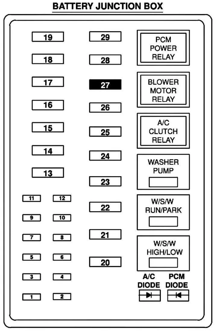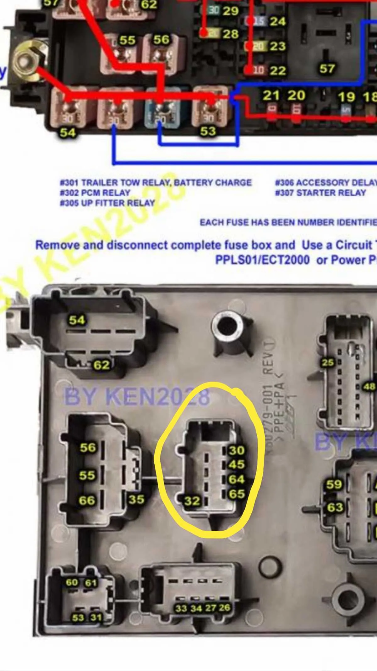
If you’re troubleshooting electrical issues, start by locating the main power distribution unit. This is essential for understanding how various systems are connected. Within this unit, you’ll find several critical relays and fuses, each responsible for specific components such as lighting, air conditioning, or the ignition system.
Identify the sections for both the engine compartment and interior cabin. Typically, the external unit will have higher amperage fuses for major systems like the engine control module and alternator, while the internal section manages lower power requirements like interior lights and radio. A quick visual inspection often helps identify blown components–check for discolored or melted parts.
Make sure to cross-reference the current specifications with a reliable source before replacing any components. A clear, labeled map will provide you with exact details on the location and amperage of each part. Always use the correct size fuse to avoid potential fire hazards or system malfunctions.
Be sure to secure the replacement part tightly, and test your vehicle’s electrical systems to confirm everything is working properly. A functioning circuit layout is key to maintaining your vehicle’s reliability and safety on the road.
Electrical Component Layout and Wiring Overview
To identify and address issues with the electrical system of your truck, it’s crucial to know the exact placement of each relay and fuse. The primary distribution point is typically located under the hood and inside the cabin. Check the main power supply area under the engine bay, where you’ll find a large set of critical relays and high-amperage connections. Inside the vehicle, the cabin unit houses the smaller, more intricate circuits for accessories and interior components.
Start with the engine compartment: this area manages power to critical systems, such as the alternator, headlights, and cooling fans. Specific slots control the flow of electricity to each component, allowing for easy troubleshooting. Consult the manual for precise details on the amperage for each slot to avoid incorrect fuse installations, which could result in system failures.
In the interior compartment, you’ll find a set of smaller relays designed to power electronics, climate controls, and safety systems. It’s essential to maintain the correct fuse ratings for each unit to prevent damage from electrical overloads. Check the condition of each fuse and relay for signs of wear or corrosion, especially in areas exposed to moisture.
When replacing a damaged component, make sure to match the replacement with the exact amperage and configuration recommended in your vehicle’s manual. Overestimating or underestimating the required amperage can lead to further electrical complications or damage to sensitive circuits.
Identifying Fuse Locations in the 2006 Ford F250 Fuse Box
To locate the correct positions of the electrical components in the main panel, refer to the inner side of the access cover. Each slot is clearly marked with a number or letter corresponding to a specific circuit. If a cover isn’t available, the vehicle’s manual provides a detailed reference with a legend to interpret these positions. It’s essential to follow the manufacturer’s layout carefully to avoid confusion between components with similar functions.
The power distribution center under the hood serves as the main location for larger fuses, which are typically associated with critical systems such as the engine, transmission, and airbags. These high-amp fuses are generally located in a square or rectangular layout. Each component should be visually identifiable, with clear labeling on both the fuse holder and the surrounding area.
For smaller circuits, the cabin area panel houses the fuses that control the interior features like lights, radio, and power accessories. It’s crucial to check the labels near the fuses for a quick identification. This panel often requires a bit more attention as the smaller components can be harder to spot. The access cover is typically located near the driver’s side, under the dash, or on the left side of the instrument panel.
Before replacing any blown elements, always confirm that the new parts match the same specifications as the original ones. This ensures proper functionality and safety for all systems connected to the circuits. Consider using a multimeter to test the components if visual checks aren’t sufficient for certain situations.
How to Troubleshoot Electrical Issues Using the Circuit Layout
Start by identifying the components controlled by the circuits in question. Locate the relay panels inside the engine compartment and cabin. Once you’ve found the correct section, compare it with the manual or the markings for each specific relay and connection point.
- Inspect any visible signs of corrosion or damage to the connections.
- Test for continuity using a multimeter. If no continuity is found, the issue is likely with the respective circuit or component.
- Verify the power flow by tracing each line according to the provided schematic, ensuring all connections are intact.
If there’s no visible damage, but the system isn’t working, check the grounding points. A loose or corroded ground can disrupt the whole system’s functionality.
- Check for blown fuses by removing and inspecting them individually.
- If any fuse is blown, replace it with one of the same amperage to avoid further electrical damage.
Next, identify components that rely on the system by looking at the affected areas. If a specific function fails (e.g., headlights or wipers), consult the relevant schematic to pinpoint the malfunctioning relay or wire.
- For complex issues, follow the layout sequentially to ensure all connections are accounted for.
- Once a fault is identified, consult the manufacturer’s guidelines for replacement or repair procedures.
Lastly, make sure all parts are properly reconnected and retested. Once the system is fully operational, confirm the connections remain stable after running the electrical components.
Understanding the Role of Each Fuse in the 2006 Ford F250

Ensure you use the correct amperage when replacing any electrical components in your vehicle to avoid damaging circuits. Check each element’s purpose before making any changes. For example, the main power supply should always be protected by a fuse rated appropriately for the current it handles.
The relay and power control section are vital for managing the electrical components such as the alternator, headlights, and transmission systems. A malfunctioning fuse here can lead to power failures or intermittent issues. Verify that each fuse is connected to a specific task, like securing the ignition, air conditioning, or braking functions. Replacing blown fuses promptly prevents further damage and ensures reliability.
In the engine area, certain fuses are responsible for engine management systems and sensors. These ensure critical parts like the fuel system, ignition, and exhaust control remain functional. Be cautious when inspecting these, as improper handling can lead to operational failures. The connections to the airbag and safety systems are another high-priority area requiring careful attention.
Interior fuses are usually dedicated to accessories such as entertainment systems, climate control, or window operation. While these issues might seem less critical, they are directly tied to comfort and convenience. Over time, components in this section might wear down and cause electrical problems, requiring a quick fuse check to avoid larger repairs.
Each fuse has a clear and distinct role within the system. It’s crucial to regularly monitor these electrical circuits to maintain the vehicle’s functionality and prevent breakdowns. For clarity, always refer to a detailed chart to understand the exact specifications and amperage requirements of each connection to ensure the vehicle operates smoothly without overloading.