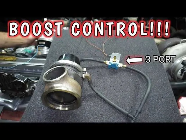
Use a T-shaped actuator unit with one input and two outputs to direct compressed air between components efficiently. This setup is ideal for alternating motion or single-acting cylinders where flow direction changes based on solenoid activation.
Connect the central inlet to your pressure source. The remaining two connectors alternate between exhaust and active output depending on coil energization. For normally closed configurations, ensure de-energized states block the air and vent the output line.
Flow reversal is achieved internally via a shuttle or poppet mechanism triggered electrically. Match the coil’s voltage to your system–common options include 12V DC, 24V DC, or 110V AC–to ensure responsive switching.
Mount the assembly close to the actuator to minimize lag. Use push-to-connect fittings for ease of maintenance and leak-free seals. Consider a model with manual override for testing without live current.
3 Port MAC Valve Diagram
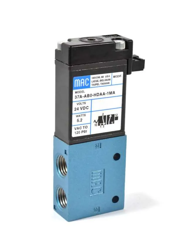
Always verify the flow orientation before installation: the central inlet directs fluid to either of the two outputs depending on solenoid actuation. Misalignment may cause operational failure or backpressure buildup.
Identification: The central channel is typically labeled “P” (pressure), while the two side channels are marked “A” and “E” (exhaust or actuator). Ensure these match the intended system routing.
Electrical control: A single coil toggles internal spool or poppet position. Use 12V or 24V DC per manufacturer spec. Incorrect voltage may lead to delayed switching or coil damage.
Mounting: Install upright to prevent debris accumulation. Use compatible brackets or DIN rail clips. Avoid overtightening to prevent cracking the base housing.
Maintenance tip: Check for contamination in the internal chamber. Foreign particles can block motion, reducing switching speed or causing a stuck condition. Clean using filtered air during scheduled service intervals.
Wiring Configuration for a 3-Way Pneumatic Actuator in Control Systems
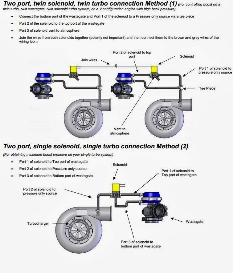
Connect the two-wire solenoid coil directly to a 12V or 24V DC power source, matching the coil’s rated voltage. Use a fused line to prevent short circuits.
- Terminal A: Positive lead from the DC supply (typically red).
- Terminal B: Negative or ground lead (typically black).
If a relay is used for isolation or control via PLC:
- Connect one coil lead to the common terminal on the relay’s output side.
- Wire the normally open contact to the positive supply line.
- Ground the remaining coil wire directly or through the relay’s negative side, depending on control logic.
Always install a flyback diode across the coil leads (cathode to positive) to suppress voltage spikes during de-energization.
Use 18 AWG stranded wire for distances under 10 meters. For longer runs, increase wire gauge to reduce voltage drop.
Label all connections and secure wires using cable ties or conduit to prevent mechanical strain. Confirm polarity and insulation before energizing the system.
Airflow Path and Switching Logic Explained with Diagram
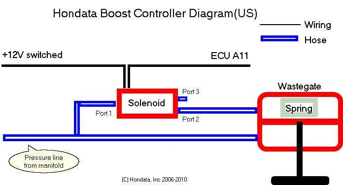
Ensure that the control signal is either fully energized or fully off–partial voltage can cause erratic behavior. In the default (de-energized) state, inlet flow enters through the main supply and exits through the primary outlet, while the secondary outlet is sealed. When actuated, the internal spool shifts, blocking the initial outlet and redirecting the stream to the alternate exhaust path.
Flow direction changes instantly based on the coil’s electromagnetic actuation. The internal chamber contains a spring-loaded shuttle mechanism that repositions depending on coil status. When current is applied, the magnetic field pulls the internal piston against the spring force, opening a new route while sealing the previous one.
Backflow prevention is automatic; check-seals close upon pressure reversal. For applications requiring rapid switching, select units with response times under 25 milliseconds and ensure supply pressure is within the recommended operating range–typically 3 to 8 bar. Avoid using lubricated air unless specified by the manufacturer to prevent seal degradation.
Troubleshooting Common Connection Errors Using Visual Guides
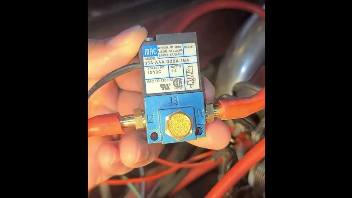
Verify flow orientation first. Ensure the inlet and outlet paths align with the directional markings on the housing. A reversed setup causes backpressure buildup or complete flow blockage.
Check actuator alignment. Misaligned actuators often result in incomplete switching. Use a side-view illustration to confirm full stroke engagement. Compare actuator position at rest and when energized.
Inspect tubing connections for consistency. Mismatched tubing sizes or loose fittings lead to leaks or delayed response. Cross-reference with exploded assembly views showing precise junction points.
Use a color-coded chart to confirm signal routing. Incorrect electrical leads can trigger unresponsive or oscillating states. Match wire colors to terminal blocks as shown in the manufacturer’s schematics.
Test for residual pressure traps. If the switching mechanism fails to reset, locate and isolate any residual air pockets using sectional cutaways. Focus on chambers with dead-end cavities.
Confirm seal integrity with visual inspection guides. Deformed O-rings or worn gaskets are often the cause of performance drop. Compare seal profiles with labeled component outlines for quick verification.
Ensure coil voltage compatibility. Refer to technical drawings specifying voltage ratings. Applying the wrong voltage creates heat stress or no actuation. Use annotated wiring guides to match ratings precisely.