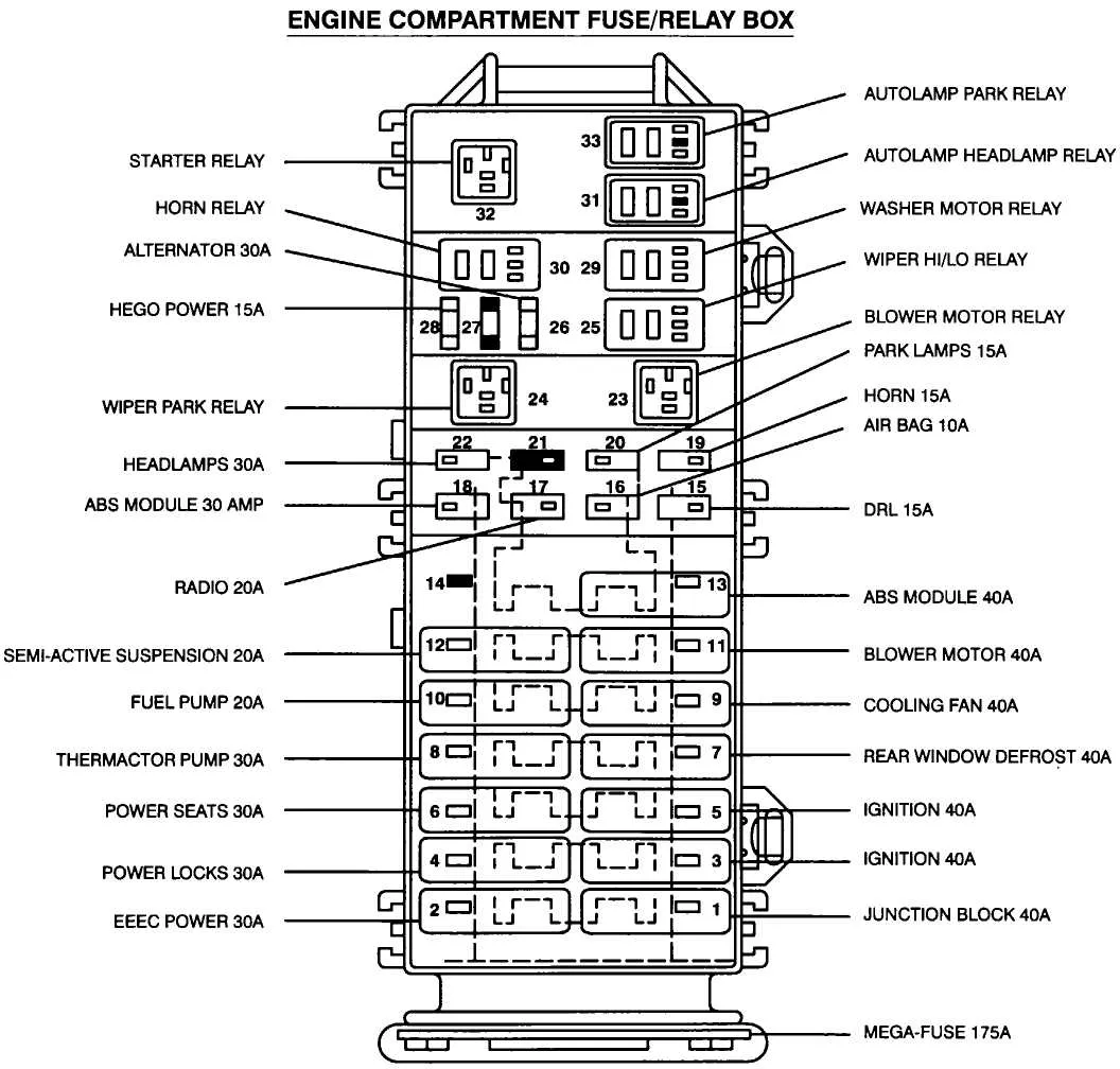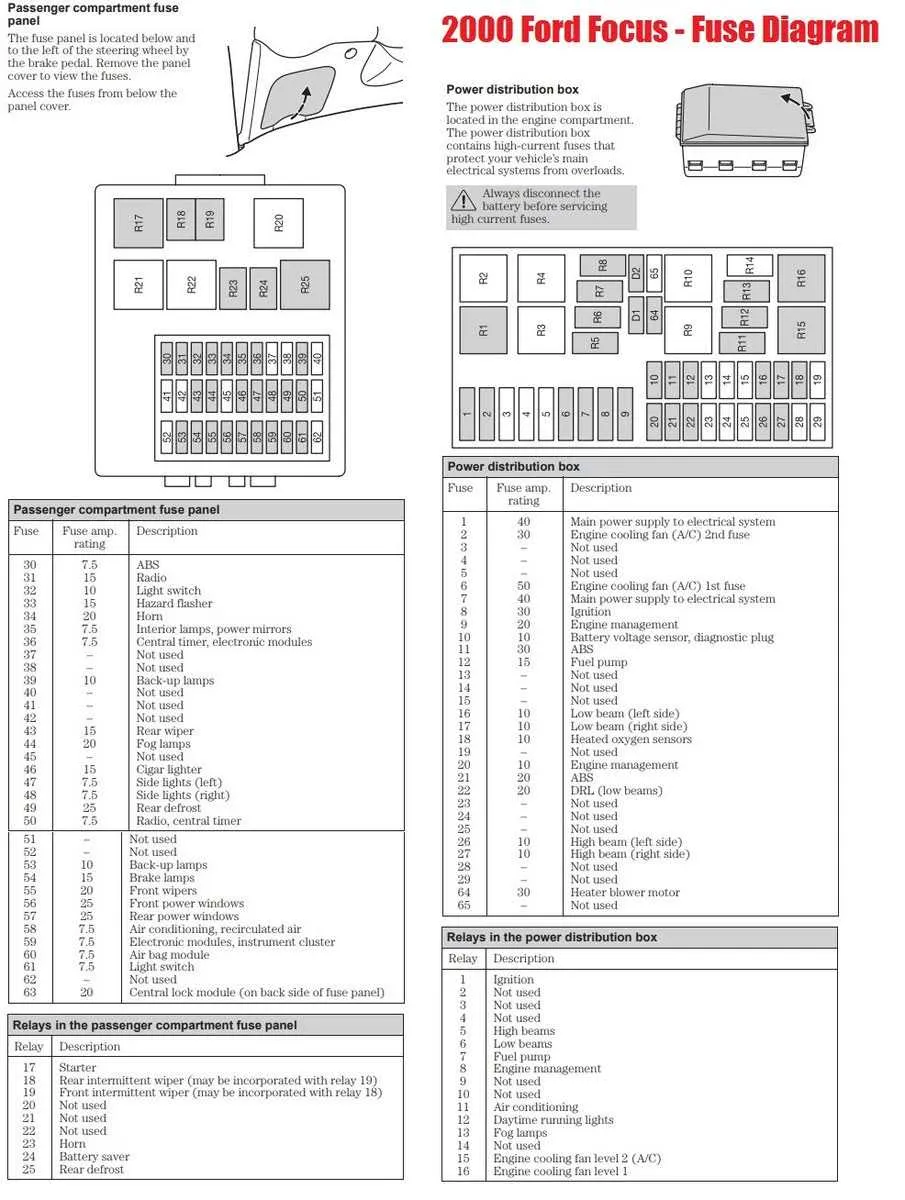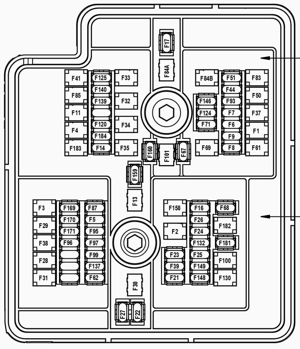
Locate the main power distribution center under the dashboard on the driver’s side for quick access to all circuit protectors. Each component is identified with clear labeling to streamline troubleshooting and replacements.
Essential circuits such as ignition, lighting, and auxiliary systems are organized to simplify diagnosis. Use the enclosed guide to identify amperage ratings and positions, ensuring the right element is serviced.
Refer to the centralized schematic to understand connections between relays and protective devices, preventing accidental replacements or misplacements. Proper knowledge of this layout reduces downtime and prevents electrical faults.
Fuse Layout for the 2008 Mustang

Locate the primary power distribution panel under the hood near the battery. The secondary panel is inside the cabin, usually beneath the dashboard on the driver’s side.
Use this guide to identify each circuit’s protection device:
- Engine Compartment Panel:
- IGN 1 – 15A, controls ignition system
- EFI – 20A, manages fuel injection unit
- H-LP LH/RH – 15A each, headlamp circuits
- ABS – 30A, anti-lock brake system
- Cooling Fan – 40A, radiator fan motor
- Interior Panel:
- Accessory – 10A, powers radio and console
- Power Seats – 25A, seat adjustment motors
- Lighting – 10A, interior illumination
- Airbag – 15A, supplemental restraint system
- Rear Defrost – 30A, rear window heater
For replacement, always use the exact amperage rating printed on the original protection device to prevent electrical issues. Avoid using higher-rated units, which risk wiring damage.
Before handling, disconnect the negative terminal of the battery to ensure safety. Refer to the cover of each panel for quick reference labels and detailed layout.
Locating and Identifying the Vehicle’s Electrical Panel
The main power distribution unit is found under the dashboard on the driver’s side, close to the kick panel area. Open the lower dash cover to reveal a black plastic enclosure secured by clips or screws.
Another secondary panel is located in the engine compartment near the battery, typically mounted on the driver’s side fender well. This unit contains high-current protection elements for engine-related circuits.
Each unit has a removable lid with a detailed layout printed on the inside, listing all circuit protections with their amperage ratings and corresponding functions. Use this guide to match individual circuit elements with vehicle components such as lighting, ignition, and accessories.
For access, use a flathead screwdriver or hands to carefully detach covers. Avoid forcing parts to prevent damage to tabs or wiring.
Check the legend for each fuse holder slot to ensure proper identification before replacement or testing. This prevents confusion between low- and high-amp circuits critical for vehicle operation.
Understanding Fuse Functions in the 2008 Ford Mustang Fuse Box
Locate the panel under the dashboard or in the engine compartment to identify the distribution of electrical protections. Each slot corresponds to a specific circuit, controlling components like headlights, horn, fuel pump, and air conditioning system.
For example, a 15-amp protection device powers the cigarette lighter and interior lights, while a 20-amp unit is assigned to the cooling fan relay. The ignition system relies on a separate 10-amp protection component to ensure proper operation.
Refer to the legend printed inside the cover to match each fuse with its purpose. Replace any burnt element with one of identical amperage to avoid damage to wiring or electrical modules. Using higher or lower ratings can lead to malfunction or safety hazards.
Regular inspection helps detect corrosion or loose contacts, which may cause intermittent failures. In case of repeated failures in the same circuit, inspect wiring harnesses and connectors for shorts or wear.
Understanding the location and function of each protection element streamlines troubleshooting and maintenance, reducing downtime and preserving system integrity.
How to Replace and Test Electrical Fuses in Your Vehicle

Locate the primary power distribution panel under the hood or inside the cabin. Remove the cover by releasing the clips or screws securing it. Identify the specific protective element that corresponds to the malfunctioning circuit using the label on the panel or the owner’s manual.
To check a blown element, use a multimeter set to continuity mode or a dedicated tester. Remove the component carefully by pulling it straight out with fuse pullers or needle-nose pliers. Place the probes on both ends of the unit; no continuity indicates it needs replacement.
Replace the defective protector with a new one of identical amperage rating. Installing a higher or lower rating can cause electrical issues or damage wiring. Ensure the new piece seats firmly in the socket and that the panel cover fits securely back in place to prevent moisture and debris intrusion.
After replacement, start the engine and test all related electrical functions to confirm restoration. If issues persist, inspect wiring harnesses and relays linked to the affected circuits.