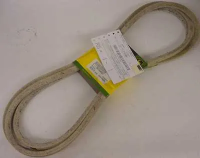
To ensure your machine operates efficiently, it is crucial to have a clear understanding of the component that transfers power from the motor to the moving parts. A proper layout of the parts involved in this mechanism can save you time and effort during repairs or replacements. The correct placement of each part allows smooth performance and minimizes wear over time.
Pay close attention to the specific alignment of the tensioner and pulleys. Any misalignment can lead to excessive friction, causing premature damage to key components. Regularly inspect for wear or fraying and replace any part showing signs of deterioration to avoid operational issues.
In the event that your system isn’t performing at optimal levels, reviewing the placement of the parts, as well as their tension and condition, will often pinpoint the issue. Always follow the manufacturer’s recommendations when replacing any component to ensure compatibility and maintain the longevity of the machine.
By properly understanding the flow of power through the system, you’ll be able to address potential issues more effectively, leading to less downtime and increased efficiency.
Engine Power Transmission System Overview

To ensure smooth operation of the power transmission system, it is essential to follow a clear path when installing the components. Start by aligning the main pulley with the smaller idler components, ensuring that there is no slack. The path of the transmission should be continuous, with minimal friction. Make sure the routing follows the factory-recommended path as shown in the instruction manual.
Key Tip: Double-check the tension on the drive mechanism after installation. A properly tensioned system reduces wear and prevents premature failure of moving parts.
The components should be placed securely to avoid unnecessary rubbing. If the components are misaligned, the operation can become inefficient and cause unnecessary strain on the parts. Pay attention to the direction of rotation when installing the pulleys and ensure they are facing the correct way.
Important Note: For precise installation, use a detailed blueprint of the power transmission system to guide your steps. Follow the route as closely as possible for optimal performance and longevity of the system. Regularly inspect for wear and tear to ensure ongoing efficiency.
Ensure the support brackets and tensioner mechanisms are in place and operate smoothly. Lack of proper adjustment can lead to slippage, reducing performance and increasing the risk of breakdowns.
Understanding the Belt Routing for the X304 Lawn Mower
When replacing the transmission mechanism on the model in question, it’s crucial to follow the exact path for the connecting elements. Start by ensuring the path runs from the pulley near the transmission to the drive pulley, crossing around the various guiding rollers along the way. Make sure to pass the component around the tensioning pulley before routing it over the crankshaft pulley. Double-check the alignment of the tensioner to avoid unnecessary wear.
Ensure the component loops through all the required support arms and rollers. These guides ensure proper operation and prevent slippage or misalignment. Pay close attention to the routing around the idler pulley and how the part feeds under the main tensioner mechanism. Incorrect routing here can result in inefficient power transfer or damage to the transmission system.
Verify that the component rests securely in all its guide slots. Proper adjustment of the tensioner arm is essential for maintaining the right tension level throughout operation. Also, take note of any directional markings on the pulley system, as these can help prevent improper alignment that could damage the entire mechanism.
After completing the routing, manually turn the drive system by hand to ensure smooth rotation without excessive friction or misalignment. If you encounter resistance, retrace the path and make necessary adjustments to the component’s positioning.
How to Replace the Engine Drive Belt on the X304 Lawn Mower
Start by raising the vehicle’s front end using a jack, ensuring it’s stable and secure. Remove the deck to access the components below. Locate the worn or damaged drive component–usually identifiable by signs of wear or snapping. Using a wrench, disconnect the battery for safety.
Afterward, use a ratchet to remove the pulley covers and loosen the fasteners that hold the assembly in place. Carefully slide the old component out from its pulleys and set it aside. Make a note of how the component was routed before removal to assist in installation.
Fit the new part by aligning it with the pulleys, following the exact route. Ensure all components are seated firmly. Tighten the fasteners securely but avoid over-tightening, as this can lead to premature wear. Reattach the deck and any other removed parts, ensuring no parts are left loose.
Before powering on, double-check all connections, including the routing of the component. Test the system by engaging the machinery at low speeds to ensure the new part operates smoothly and without resistance. If everything works correctly, lower the vehicle back to the ground.
Common Issues and Troubleshooting Tips for the X304 Drive Belt

When the power transmission system is malfunctioning, it is often related to improper tension, wear, or damage to the components involved in power transfer. Here are some common issues and how to address them:
- Slipping – If the power transfer is inconsistent or the system fails to engage, check for excessive slack in the mechanism. Adjust the tension or inspect the pulley system for wear. If the pulleys are worn unevenly, replacement may be necessary.
- No Power Transmission – If the unit doesn’t operate despite engaging the throttle, inspect the tension and alignment of the components. Misalignment can prevent proper transfer. Ensure all parts are secured tightly and free of obstructions.
- Excessive Noise – A noisy mechanism can indicate a misaligned pulley or wear on the friction surface. Lubricate moving parts, check for obstructions, and examine the wear patterns on the contact surfaces.
- Excessive Vibration – Uneven wear or damaged pulleys can cause vibration. Inspect for cracks or signs of wear on the pulleys and replace any damaged parts. Ensure the system is properly aligned to reduce unnecessary strain on the components.
- Fraying or Damage – Inspect the tension system for visible damage. If fraying or tearing is found, replace the affected part immediately to avoid further damage to the system.
- Overheating – Overheating can result from insufficient lubrication or excessive friction. Check the contact points and lubricate where necessary. Additionally, ensure that all air passages are clear to allow for proper cooling.
Regular maintenance, such as adjusting tension, inspecting for damage, and cleaning, is key to ensuring long-term functionality. If the system continues to malfunction despite following these steps, consult a technician for further diagnosis.