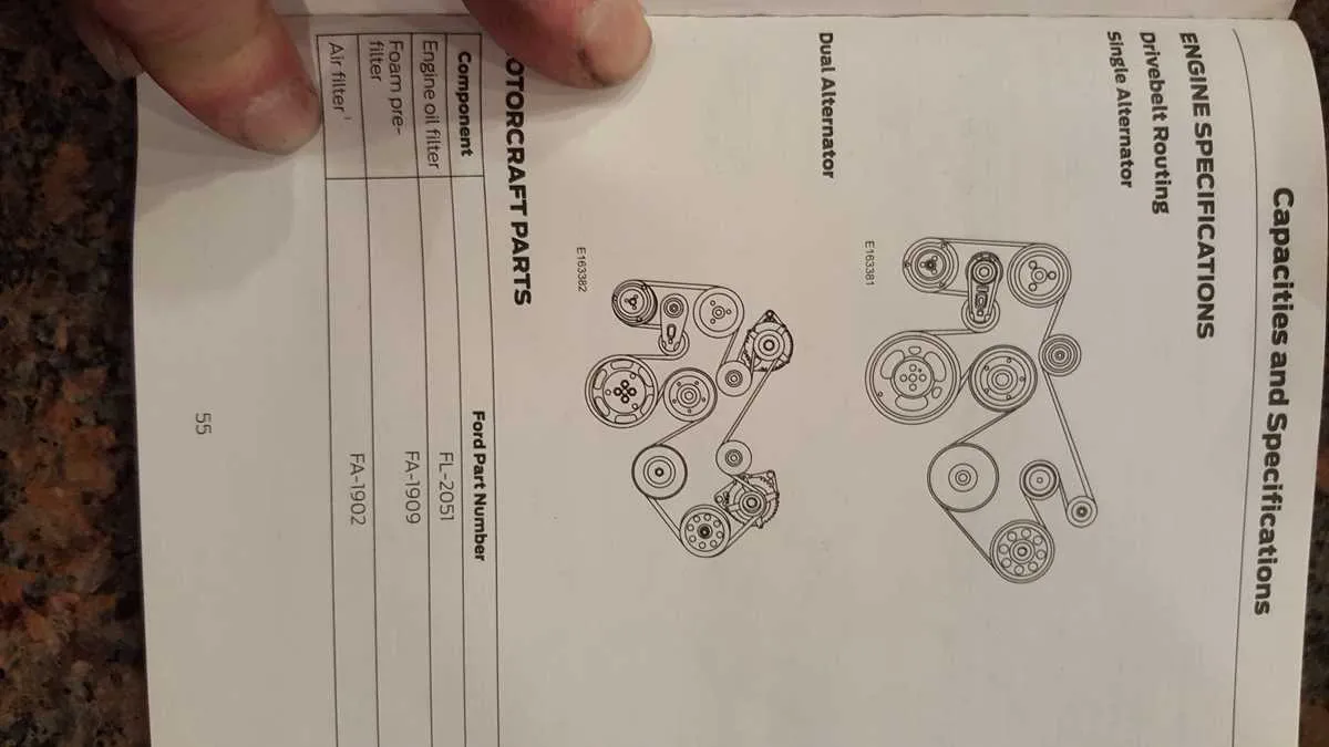
Begin with aligning the tensioner pulley clockwise using a breaker bar to relieve pressure before removing the worn drive component. This step prevents accidental misrouting and ensures safe disassembly.
Ensure that the crankshaft rotation is synchronized with the alternator, fan clutch, and both idler assemblies. A typical layout passes the loop around the A/C compressor, then under the water pump, continuing over the generator unit.
Route the new component starting from the bottom at the harmonic balancer, progressing upward to the air compressor and steering pump. Confirm it bypasses the secondary idler unless the configuration includes a dual alternator setup.
Always verify alignment along the tension side before releasing the tensioner. Misalignment at the vacuum pump or auxiliary pulleys may lead to premature failure or system noise under load.
Double-check the configuration by referencing the under-hood sticker or service manual specific to your diesel variant. Using an incorrect routing sequence can disrupt coolant flow and charging efficiency.
Drive Routing Layout and Tensioner Positioning
Start by verifying the serpentine routing from the crankshaft pulley, which should lead to the dual-groove alternator, then wrap under the A/C compressor and over the water pump. Ensure the path proceeds counterclockwise past the idler before reaching the power steering component.
The automatic tensioner sits directly beneath the fan pulley. Rotate it clockwise using a 15mm socket to relieve pressure during removal or installation. Confirm that the spring-loaded mechanism returns smoothly to its default state, indicating proper function.
Double-check alignment over the secondary idler near the fan clutch. Misalignment here often causes fraying or squealing. Tension should remain firm–between 140 and 160 pounds-force–once installed. Replace worn rollers immediately to prevent premature failure of driven accessories.
How to Locate and Identify All Belt-Driven Components on the 6.7L Diesel Engine
Start by removing the upper fan shroud to expose the front drive system. Use a 1/2-inch breaker bar to relieve tension from the serpentine routing, allowing better visibility and access.
- Alternator: Positioned on the upper passenger side, secured with two bolts and connected via a multi-pin plug and a battery cable.
- Fan clutch: Mounted directly to the water pump shaft; requires a special tool for removal. Clutch pulley is centrally located and connected to the cooling fan.
- Water pump: Found at the center front, just below the thermostat housing. Driven by a large pulley that also supports the fan assembly.
- Air conditioning compressor: Lower passenger side, distinguishable by dual refrigerant lines and electrical connectors. Mounting bracket is attached to the front engine cover.
- Power steering pump: Upper driver’s side, with a smaller pulley. Connected via high-pressure and return fluid lines to the steering system.
- Idler pulleys: There are two – one located just above the crankshaft and another between the alternator and tensioner. Both are stationary and guide the drive loop.
- Tensioner assembly: Found on the lower driver’s side. Spring-loaded arm with a smooth pulley used to maintain optimal routing pressure.
- Crankshaft pulley: Lowest point of the front assembly, directly connected to the harmonic balancer. Drives all accessories via a multi-groove track.
Double-check routing alignment using the sticker on the radiator shroud or service manual reference. Ensure all pulleys are free of debris and spin without resistance before reassembly.
Step-by-Step Guide to Routing the Serpentine Belt Correctly
Start by rotating the tensioner pulley clockwise using a 1/2-inch drive ratchet inserted into the square hole. This relieves pressure, allowing easy removal of the old loop.
Ensure the replacement unit matches the OEM specification: same length, rib count, and profile. Mismatched components can cause slippage or premature failure.
Position the new loop around the crankshaft gear first. Then guide it around the water pump, ensuring the ribs align perfectly with the grooves.
Wrap the next section over the alternator. Continue by slipping it beneath the idler roller, followed by the A/C compressor if equipped.
Route the smooth side of the band over any flat pulleys. Grooved sections must contact only ribbed surfaces to maintain traction and prevent noise.
Leave the tensioner for last. With the tool still holding it back, slide the final portion into place, then gently release the tool to apply tension.
Double-check alignment across all rollers. Misalignment as small as 1/16 inch can lead to wear, noise, or total system failure.
Manually rotate the crankshaft two full turns clockwise to verify smooth movement and correct tracking across all contact points.
Common Belt Alignment Issues and How to Diagnose Them
Inspect pulley surfaces for uneven wear. Any signs of glazing, chipping, or off-center grooves indicate misalignment or improper installation. Use a straightedge tool across multiple pulleys to confirm alignment within a 1/16-inch variance.
Check tensioner angle under load. If the tensioner arm does not maintain a consistent angle or appears skewed, the component may be defective or incorrectly mounted. A worn spring inside the assembly can also lead to vibration and slippage.
Listen for high-pitched squeals on startup. This typically signals sideways tracking, often caused by a bent bracket or incorrect torque on mounting bolts. Pinpoint the source using a mechanic’s stethoscope or by temporarily applying water to the ribbed surface to check noise response.
Monitor tracking path during engine idle. Use a UV dye marker or chalk line on the ribbed side and observe movement after a few minutes of operation. If the mark shifts laterally, it confirms axial misalignment or faulty bearings in a driven accessory.
Verify proper component spacing. Use OEM specifications to measure the gap between accessory housings and adjacent mounts. Any deviation can distort the routing path and lead to premature degradation of the routing element.