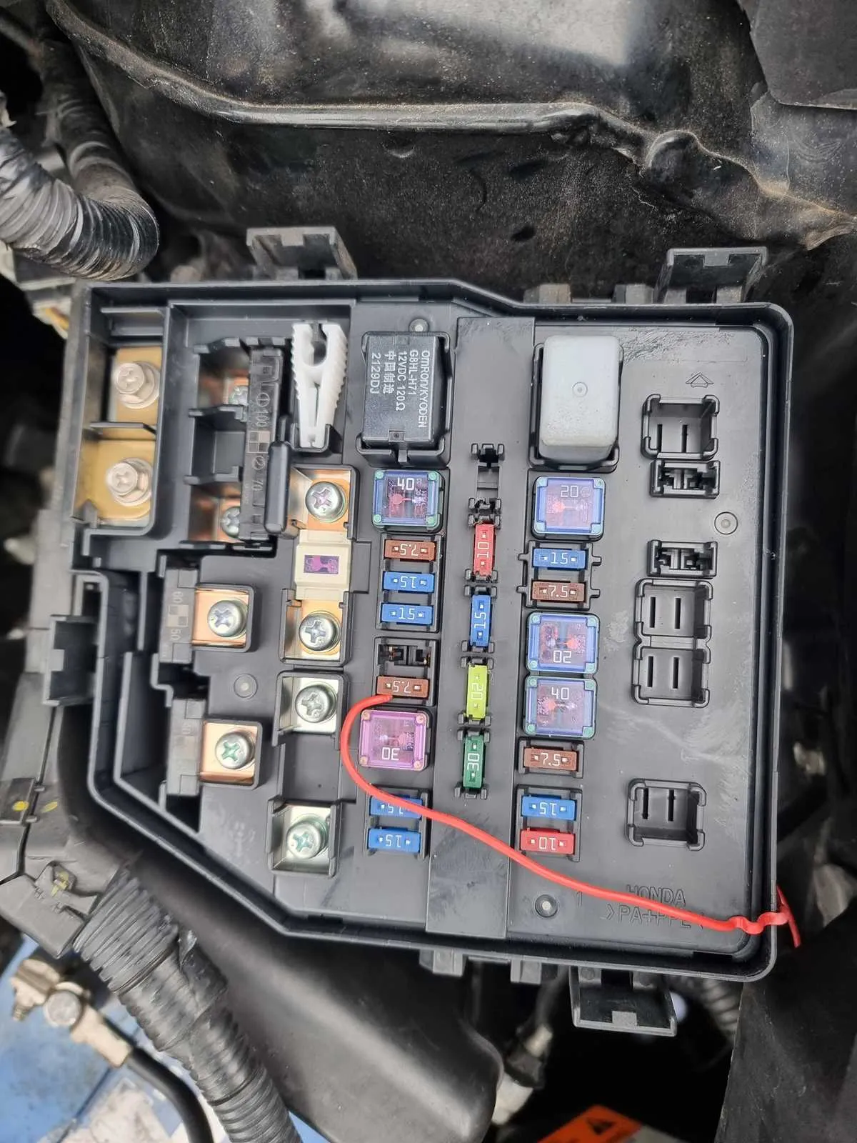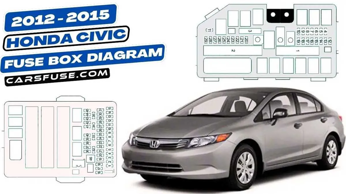
Begin inspection by locating the under-hood junction unit, positioned adjacent to the battery compartment. This enclosure houses high-amperage circuit regulators responsible for essential systems such as ignition coils, cooling fan motors, and the fuel injection control. Use the internal cover chart to match terminal numbers with their respective systems.
Inside the cabin, remove the panel beneath the steering column to access the dashboard switchboard. Here, secondary protection devices for components like the windshield wiper motor, interior lighting, and power sockets are arranged in a linear array. Identify each socket by the numbering etched into the plastic housing for precise troubleshooting.
Check the rear compartment distribution box near the trunk liner if experiencing issues with tail lamps or reverse indicators. This rear array typically contains low-current fuses and a few micro-control switches managed by the onboard body control unit. Replace only with components matching the specified amperage to prevent circuitry imbalance.
For maintenance, refer to the vehicle’s technical reference guide for terminal designations such as IG1, ACC, and FAN to avoid misplacement. Using a multimeter, measure voltage at each point to ensure proper signal delivery during diagnostics.
Engine Bay Fuse Panel Layout and Key Module Connections
Start by locating the main fuse enclosure beneath the hood on the driver’s side, adjacent to the strut tower. Remove the plastic cover to reveal the circuit control units. The fuel injection power switch is situated in the upper right corner, marked with a 15A fuse and a compact cube-shaped switch labeled FI MAIN.
Starter activation control is positioned near the lower section, paired with a 30A fusible link marked ST MG. This component interacts directly with the ignition key cylinder through the neutral safety switch.
Cooling system control resides in the midsection of the enclosure. It is linked to a 20A fuse (COND FAN) and triggers the radiator fan motor under high temperature or A/C load. Next to it, a secondary controller manages the condenser fan via the AC FAN module.
Inside the cabin, beneath the left dashboard panel, the interior power grid hosts accessories like power windows, horn, and turn indicators. The small black box labeled IG1 controls ignition-on power distribution. Adjacent to it, a compact module labeled HAZ/HORN handles alert sounds and emergency blinkers.
Always consult the fuse box cover for the legend. Replace any faulty control cube with the identical amperage and configuration to avoid circuit failure or component damage.
Locating the Under-Hood Fuse and Relay Box

Open the front hood and focus on the passenger-side corner near the firewall. The enclosure you’re looking for is a rectangular black box with a removable lid, typically secured with small clips or tabs.
Look for embossed labeling on the cover, such as “FUSE BOX” or a symbol indicating electrical components. This container is mounted on the inner fender or adjacent to the battery compartment, depending on the trim configuration.
Release the fasteners carefully using a flat-head screwdriver or by hand pressure. Inspect the underside of the lid; it contains a schematic key for component identification and amperage ratings. Ensure the ignition is off before accessing this unit to avoid shorts or accidental engagement of electrical systems.
Identifying Key Relays for Starter, A/C, and Fuel Pump

Begin by locating the under-hood power distribution module on the driver’s side near the strut tower. For engine cranking issues, inspect the black square component labeled “STR.” It typically resides in the top-left corner of the compartment and is energized when the ignition switch reaches the start position.
Cooling system and cabin airflow concerns often trace back to the unit marked “MG CLT.” Positioned centrally in the fuse array, this block controls compressor engagement and must receive both ECU signal and proper ground to function. Check for continuity and replace if resistance exceeds manufacturer tolerance.
Fuel supply interruptions usually involve the component tagged “FI MAIN.” Found on the lower right of the panel, this unit activates with ignition ON and enables pump priming. Use a multimeter to verify voltage at pin terminals; absence of 12V during key-on indicates failure or associated wiring fault.
Troubleshooting Switching Component Issues Using the Wiring Map
Begin by identifying the specific electromagnetic switch responsible for the circuit malfunction through the schematic. Follow these steps for precise diagnosis:
- Locate the coil terminals and measure resistance with a multimeter; values significantly outside the standard range (typically 50-120 ohms) indicate a faulty coil.
- Check for proper voltage supply at the control side of the switch during activation; absence of voltage suggests wiring or control module issues.
- Inspect the load terminals for continuity when the switch is energized; open circuit or high resistance here points to internal contact failure.
- Verify grounding points connected to the switch coil or control circuit; poor ground can cause intermittent operation.
- Examine fuses and connectors upstream to rule out power delivery problems affecting the switch’s function.
Utilize the detailed pinout from the electrical layout to confirm exact terminal assignments, avoiding miswiring and ensuring accurate testing points. Always cross-reference with connector identification codes and wire color codes to prevent diagnostic errors.
- Test coil activation voltage under both key-on and engine-running conditions.
- Swap suspected malfunctioning units with known good equivalents to isolate mechanical versus electrical faults.
- Use a 12V power source to manually energize the coil and observe mechanical clicking or circuit continuity.
Applying these targeted checks based on the circuit map ensures efficient resolution of switch-related failures without unnecessary component replacements.