If you’re experiencing issues with your car’s electrical system, start by reviewing the key components that manage the current flow to various systems. The electrical system’s central hub plays a crucial role in distributing power efficiently. Understanding the location and function of each relay and connection is essential for resolving common faults.
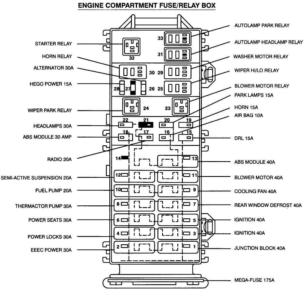
For an in-depth understanding, locate the control unit that houses the relays for the engine, transmission, and additional systems. The central relay center is typically found near the engine bay or under the dashboard, depending on the vehicle’s model. Each connection is labeled with specific functions, making it easier to identify which part needs attention.
It’s important to examine the connectors carefully for corrosion or damage. Faulty connections can lead to electrical failures, from engine stalling to non-functioning accessories. Replace any worn or broken parts immediately to prevent further complications.
Always follow the manufacturer’s guidelines for replacing fuses and relays to ensure optimal vehicle performance and avoid accidental short circuits. Regular maintenance of these components will help extend the life of your car’s electrical system.
Electrical System Layout for V6 Model
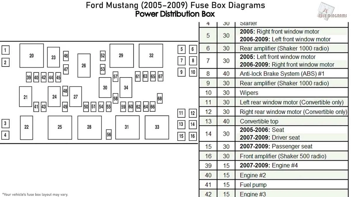
To locate the power distribution components in your vehicle, check the primary electrical panel in the engine compartment. It houses several critical relays and circuits essential for engine performance, lighting, and onboard accessories.
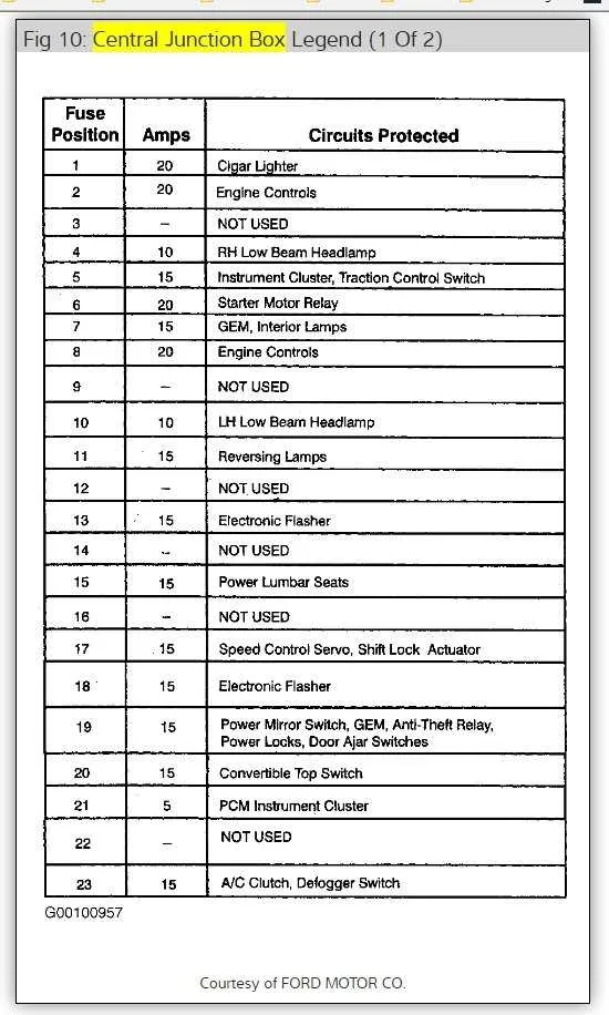
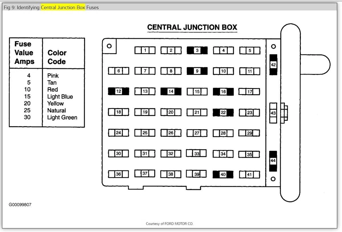
For interior functions, such as dashboard features and HVAC system, refer to the secondary unit, usually placed beneath the dashboard on the driver’s side. This unit manages most of the car’s smaller electronics and security features.
If you’re troubleshooting an electrical issue, it’s advisable to inspect both the main and secondary units, as they control different systems. Each section has labeled positions for relays and fuses, providing a clear identification of which circuit corresponds to each system. Always follow the vehicle’s service manual for accurate placement details and specifications for replacing damaged components.
When replacing or checking components, ensure the vehicle is turned off to prevent electrical short-circuits. Be mindful of the amperage ratings for each component to avoid overloading the circuits.
Refer to the specific manual for additional guidance on each unit’s layout and function. If in doubt, consulting with a professional can help in maintaining the integrity of the electrical systems in your vehicle.
Locating the Fuse Panel in a V6 Model

To find the electrical panel in a V6 model, begin by opening the driver’s side door. Look under the dashboard, near the left side of the steering column. The access cover is typically secured with clips or screws, making it easy to remove when necessary. In most cases, the assembly is located directly beneath the instrument cluster for quick reach.
Another crucial location is under the hood. Open the engine compartment and locate the main electrical unit on the passenger side. This assembly is often housed in a plastic compartment, secured by a latch or clips for safe operation and maintenance. Carefully lift the cover to access the circuit connections for engine and auxiliary systems.
Both panels serve different purposes, with the one under the hood managing high-voltage components, while the interior unit handles cabin and low-power accessories. It’s essential to refer to the layout guide inside each panel for accurate identification of each fuse and relay.
Understanding the Function of Each Circuit Protection Component

Each electrical circuit within a vehicle relies on specific components to ensure safety and prevent damage from power surges. Below are key points regarding the operation and role of each protective element in the system.
- Powertrain Control Module (PCM): Ensures that critical systems like the engine and transmission are functioning correctly by regulating electrical flow. If an issue arises, the protective component cuts off power to prevent further damage.
- Headlight System: This component safeguards the front lighting system, shutting off power when electrical malfunctions are detected, preventing potential fires or damage to the headlamps.
- Climate Control System: Protects circuits that regulate cabin temperature. If the fan system or sensors experience issues, this component stops the flow of current to prevent overheating or short circuits.
- ABS and Traction Control: These safety features rely on their own protection elements to avoid electrical damage in the event of a malfunction in the wheel sensors or control unit.
- Ignition System: The component connected to the ignition system prevents high-current damage by cutting off power in case of ignition failure or faulty wiring.
When replacing or inspecting components, it’s crucial to refer to the exact specifications of each protective element. Using the wrong component could lead to further malfunctions or even damage the entire electrical network.
- Visual Inspection: Always check for visible signs of wear or burn marks, which can indicate a malfunction.
- Testing Voltage: Use a multimeter to ensure the component is correctly distributing voltage.
- Replacement: When replacing, ensure the new component matches the required amperage rating to maintain vehicle safety and functionality.
Maintaining and understanding the purpose of each part is key to ensuring the vehicle operates safely and reliably.
Troubleshooting Common Electrical Panel Issues in the 2016 Ford Mustang V6

When experiencing electrical issues, the first step is to inspect the panel for any visibly damaged components or blown circuits. Begin by checking the relays and connectors for signs of wear, corrosion, or loose connections. Make sure all pins are properly seated in their sockets.
If a particular electrical system, like the headlights or radio, is malfunctioning, focus on the specific area related to that circuit. Use a multimeter to measure voltage levels across the relevant connectors. A drop in voltage can indicate a blown component or faulty wiring that needs to be replaced.
If there are recurring problems or the panel is unresponsive, verify the condition of the main power distribution unit. This could be a source of power failure, requiring either a repair or replacement of certain internal parts to restore functionality.
In the case of intermittent electrical failures, inspect the ground connections for any loose or corroded spots. Poor grounding can cause unpredictable behavior, leading to short circuits or incomplete electrical functions. Ensure that all ground straps are secure and free from damage.
For more severe issues, consider checking the interior electrical control systems for software or sensor malfunctions. A diagnostic tool may be required to scan for any error codes and pinpoint the exact issue causing system failures.