To ensure seamless transition between primary and backup energy supplies, it is vital to correctly understand and implement wiring layouts for automatic load transfer devices. Proper configuration minimizes downtime and prevents damage to connected equipment.
Key components include the main power inlet, generator connection, control relay circuits, and load terminals. Identifying each element on the schematic allows for accurate troubleshooting and safe installation.
Wiring paths must comply with applicable standards, ensuring that signal and power lines are isolated appropriately to avoid interference or malfunction. Detailed schematics assist technicians in verifying correct sequencing of contacts during source switching.
Including protective elements like circuit breakers and surge suppressors in the layout guarantees enhanced safety and longevity of the power management system. Clear labeling of connections within the layout reduces errors during maintenance and upgrades.
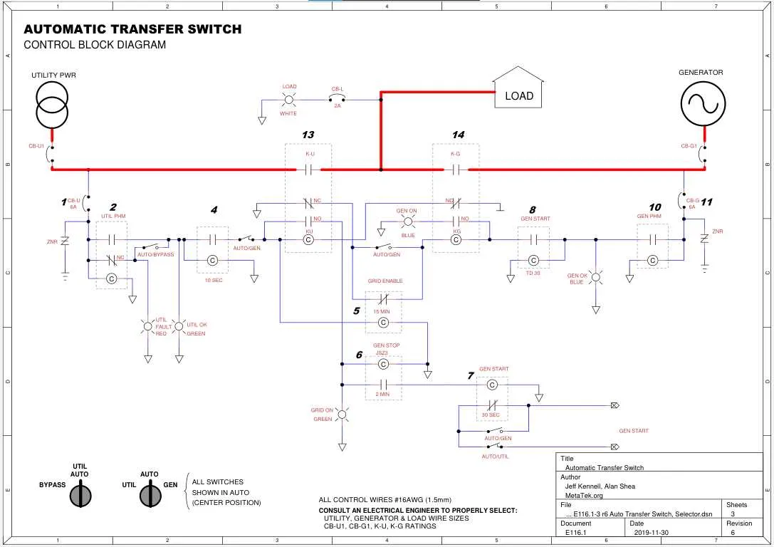
Power Source Changeover Circuit Layout
Ensure proper wiring between the main utility line, generator input, and load bus. The control module must receive signals from both power sources to detect voltage presence and quality. Use three-pole contactors or relays rated for the load current to handle source switching.
The layout includes a control coil energized by the primary supply, which de-energizes to activate the backup source contactor. Integrate voltage sensing relays with adjustable thresholds to prevent switching during transient dips or spikes.
Incorporate interlocking contacts mechanically or electrically to avoid simultaneous closure of both sources, preventing short circuits. Use fuses or circuit breakers at each input for overcurrent protection.
Design the schematic to include an input selector relay controlled by the sensing unit, which commands the changeover mechanism. Include indicators for source status and position of the output contacts.
Follow manufacturer specifications for coil voltages and contact ratings. Label all connections clearly to simplify troubleshooting and maintenance. Test the system under simulated power failure conditions to verify correct sequencing and timing.
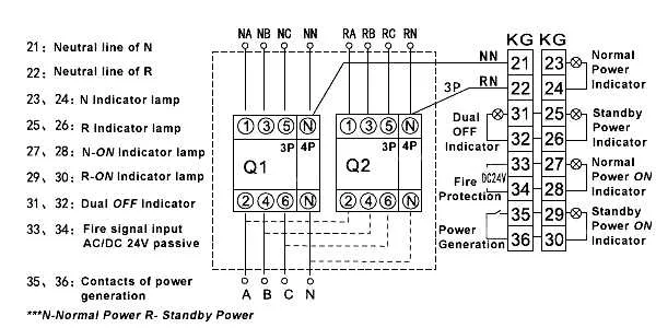
Wiring Connections for ATS Input and Output Terminals

Ensure proper terminal identification before connecting. The input terminals are typically labeled as “Line” or “Utility,” while the output terminals correspond to “Load” or “Generator.” These terminals should be clearly marked, and it is essential to match the wire size according to the current ratings specified in the unit’s manual.
For input connections, use appropriate cable types rated for high voltage and current. When connecting the neutral wire, ensure it is properly secured in its dedicated terminal, as improper connections here can lead to ground loops or equipment damage. For single-phase systems, the phase wire should be connected directly to the input terminal, while the ground wire must be connected to the designated ground point to prevent electrical shock risks.
On the output side, connect the load wires securely to the designated output terminals. Each wire should be tightened to the manufacturer’s torque specifications to ensure reliable operation and minimize the risk of overheating. In multi-phase setups, confirm that each phase is properly connected and balanced to avoid overloading any phase. Keep the neutral and ground conductors isolated unless explicitly instructed otherwise in the unit’s guide.
Double-check the terminal screws and ensure they are not over-tightened, as this may damage the terminals or cause stress on the wire. Lastly, test all connections thoroughly before powering on the system to avoid failures during operation.
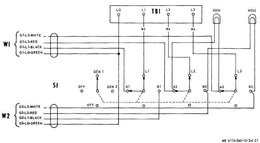
Interpreting Control Circuit Symbols in ATS Diagrams

Focus on understanding the functional roles of each component, such as relays, contactors, and fuses. Identify the control voltage source and the load-side connections to correctly interpret the flow of current. Pay close attention to the numbering system for contacts, as it indicates the switching sequence–normally open or normally closed positions.
Symbols for relays often resemble a coil with two parallel lines, while contactors are depicted with a coil and associated switch positions. A break in the circuit usually signals a control condition such as a fault or an intentional disconnect. Refer to standard codes and legends specific to your system for accuracy when analyzing these symbols.
Ensure proper identification of power and auxiliary circuits within the schematic. The auxiliary circuit might have its own symbols, often related to monitoring and protection devices, such as thermistors or overload protection. Understanding these distinctions is crucial for troubleshooting and ensuring the system operates as intended.
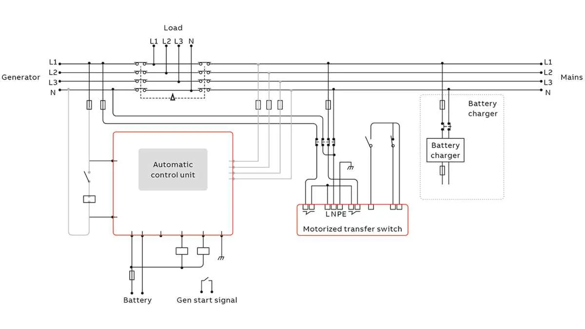
Step-by-step layout for integrating ATS with generator and mains

To ensure smooth operation between the generator and mains power supply, follow this systematic guide to integrate the device with both systems.
- Confirm system requirements: Ensure that the generator’s power output and the mains’ voltage specifications match the load’s demands.
- Prepare the generator: Connect the generator’s output terminals to the designated input terminal on the device. Verify that the generator is properly grounded.
- Set up connections to the mains: Link the mains input terminals to the main panel. Ensure that the proper circuit breakers are in place to protect the system.
- Link the device to the load: Connect the output terminals of the device to the load, ensuring the load does not exceed the capacity of the unit. Double-check wiring connections for accuracy.
- Integrate the control system: Connect the control panel to both the generator and mains, ensuring the control system is configured to automatically switch between the two power sources as required.
- Test the system: Simulate a power failure by disconnecting the mains supply. Verify that the generator powers up and the device switches the load automatically to the generator. Reconnect the mains and confirm the device returns the load to the mains smoothly.
- Set up monitoring and maintenance protocols: Regularly monitor the functionality of both power sources and the integration system. Schedule maintenance to ensure reliability during power interruptions.