When working with this specific powerplant, it’s crucial to have a clear grasp of the key components and their arrangement. The unit operates through a combination of precision engineering, where every part plays a vital role in overall performance. Ensuring proper understanding of its layout will assist in maintenance, troubleshooting, and optimizing its output.
The top of the system includes the intake manifold, which channels air into the cylinders, while the fuel delivery system ensures each chamber receives the correct mixture for combustion. Be mindful of the spark plugs, located strategically to ignite the fuel-air blend at the precise moment, crucial for optimal combustion efficiency.
For effective diagnostics, familiarize yourself with the valve timing system and how it adjusts the intake and exhaust valve openings. This system significantly impacts power output and fuel economy, making regular checks and adjustments an essential part of upkeep. Similarly, attention to the cooling system components, such as the thermostat and water pump, will prevent overheating and ensure longevity of the internal elements.
Engine Layout Overview
To understand the structure and components of a 4-cylinder powertrain, focus on the key sections such as the intake manifold, combustion chamber, crankshaft, and camshaft positioning. The intake manifold is responsible for delivering air to the combustion chambers, where the fuel is mixed and ignited. Pay attention to the timing mechanism that synchronizes valve operations and fuel delivery for optimal performance.
The cylinder block houses the pistons and plays a vital role in generating mechanical force. Proper alignment and balanced airflow within the block ensure efficient energy conversion. The camshaft, which operates the engine’s intake and exhaust valves, is a critical component that must be correctly calibrated to maximize efficiency. Its position relative to the crankshaft is essential for proper timing and combustion efficiency.
Additionally, the cooling system, including the radiator and thermostat, maintains optimal operating temperatures to prevent overheating and ensure longevity. A high-performance ignition system is also vital for reliable spark delivery to the cylinders, ensuring smooth engine operation across varying RPM ranges.
Detailed Overview of 4.3 Vortec Engine Components
The key components of this powerplant include the block, cylinder heads, and valve train system. The block is constructed with cast iron, providing durability and strength for long-lasting performance. It’s designed to handle high pressures and provide efficient power transfer.
Each cylinder head is engineered with precision to optimize airflow, with intake and exhaust ports carefully shaped to improve combustion efficiency. The valves, which are controlled by a pushrod system, are driven by a camshaft positioned in the center of the block.
The fuel delivery system uses a multi-port injection setup to ensure precise fuel management. This system is combined with an electronic control unit (ECU) to regulate fuel mixture and timing, adjusting according to engine load and operating conditions.
The ignition system incorporates coil-on-plug technology, providing better spark control and more reliable starts. The timing of ignition is synchronized with the intake and exhaust strokes to maximize performance and minimize fuel consumption.
The cooling system is designed with an aluminum radiator and a thermostat-controlled water pump to maintain optimal temperatures during operation. The engine uses a serpentine belt to drive the accessories like the alternator, power steering pump, and air conditioning compressor.
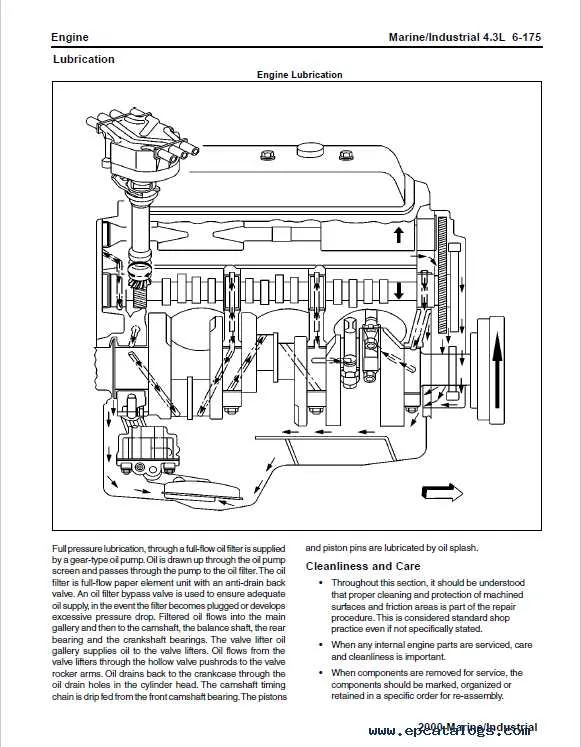
Additionally, the lubrication system ensures smooth operation by distributing oil to key moving parts like pistons and crankshafts. The oil pump is designed to provide consistent pressure to prevent friction and excessive wear, enhancing the longevity of internal components.
For exhaust management, this power unit is fitted with a set of tubular manifolds that help direct exhaust gases away efficiently, reducing back pressure and improving engine efficiency. The exhaust system works seamlessly with the catalytic converter to reduce emissions and maintain environmental standards.
Understanding the Role of Each Key Part in Vehicle Operation
The key components in a motor system are essential for its smooth functioning. Each part has a specific task that ensures efficient power production and transfer. Below are the crucial elements and their roles:
- Crankshaft: Transforms the linear motion of the pistons into rotational force, allowing the vehicle to move.
- Pistons: Move up and down within the cylinders, compressing the air-fuel mixture to generate power.
- Camshaft: Regulates the timing of the intake and exhaust valves, coordinating with the crankshaft for optimal performance.
- Valves: Intake valves allow the air-fuel mixture in, while exhaust valves release the burnt gases after combustion.
- Timing Chain/Belt: Synchronizes the movements of the crankshaft and camshaft, ensuring accurate valve operation.
- Fuel Injectors: Deliver a precise amount of fuel into the combustion chamber, ensuring an efficient burn.
- Ignition System: Initiates combustion by creating a spark in the cylinder at the right moment.
- Cooling System: Prevents overheating by circulating coolant to absorb and dissipate excess heat from the combustion process.
Each of these components must work in harmony to ensure efficient power production and optimal performance. Regular maintenance and timely replacements can prevent system failures and improve vehicle longevity.
Common Wiring and Connection Points in the V6 Powertrain

Ensure proper grounding of the ignition system by connecting the negative terminal of the battery to the engine block. A poor connection can lead to misfires and performance issues.
The fuel injectors are controlled by a dedicated wiring harness that connects to the powertrain control module (PCM). Verify the harness connections to ensure consistent fuel delivery to each cylinder.
The mass airflow sensor (MAF) is a critical component for fuel management. The wiring for the MAF sensor should be securely connected to the PCM for accurate air intake measurements, avoiding potential issues with fuel-air mixture adjustments.
The throttle position sensor (TPS) wiring should be checked for signs of wear or damage. Ensure that the sensor’s connector is properly seated to maintain smooth throttle response and prevent erratic idle behavior.
The crankshaft position sensor sends timing data to the PCM. Check the wiring connection for continuity, as a faulty connection could result in engine timing errors, leading to poor performance or even a no-start condition.
The alternator connection should be verified regularly to ensure that the charging system is functioning. A loose or corroded alternator wiring can result in undercharging, affecting battery life and electrical system reliability.
Inspect the oxygen sensor wiring carefully. A faulty oxygen sensor or damaged wiring can cause inaccurate emissions readings and disrupt fuel efficiency. Ensure a secure connection to prevent diagnostic trouble codes (DTCs) from triggering.
Lastly, check the connections to the starter motor. The positive cable from the battery should connect directly to the starter, while the ground should be attached to a clean engine block surface. Poor connections can cause intermittent starting issues.