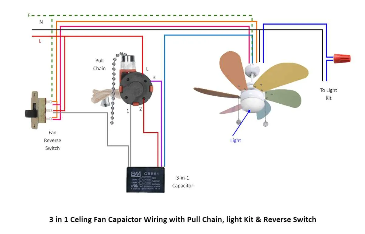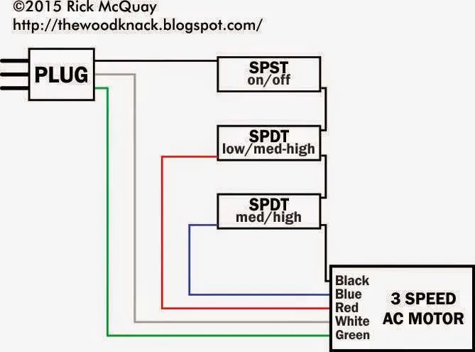
To ensure proper function of a four-level ventilation unit, connect the power leads according to their designated terminals. Typically, each phase corresponds to a distinct wire color: black for high, blue for medium-high, red for medium-low, and yellow for low settings. The neutral is usually white, while the ground should connect to the chassis or green wire.
Accurate terminal identification is critical. Use a multimeter to verify continuity before securing any connectors. Avoid mixing the lead order, as incorrect hookup can cause the device to operate improperly or even fail.
For models with integrated capacitors, attach the start wire to the appropriate terminal marked “start” or “S.” Ensure all connections are tight and insulated to prevent shorts or electrical hazards. Refer to manufacturer-specific labels or markings for exact pin assignments.
Consistent labeling and methodical approach will simplify troubleshooting and maintenance in the future, saving time and reducing errors during installation or replacement procedures.
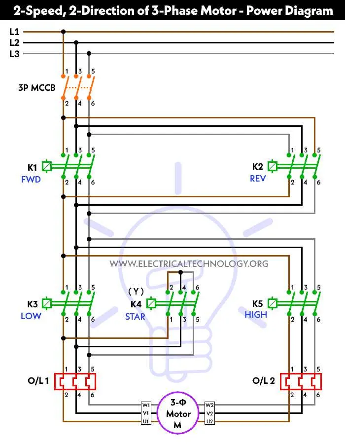
4-Speed Fan Assembly Electrical Connection Scheme

Connect the four output leads to the corresponding terminals marked as low, medium-low, medium-high, and high on the HVAC unit. Use a common neutral wire for all settings to complete the circuit.
The power feed should be routed from the fuse or relay box to the control switch input terminal, ensuring proper insulation and secure terminals. Typically, the control switch includes four separate contacts that select the desired operational level by directing current to one of the four coil taps within the rotor assembly.
Grounding must be established on the frame or chassis to prevent electrical faults. Use a multimeter to verify continuity between the ground wire and the vehicle body.
For troubleshooting, verify voltage at each output lead relative to ground while cycling through the different control positions. Absence of voltage on any terminal indicates a fault in the control switch or a break in the connecting cable.
Ensure all connectors are corrosion-free and fastened tightly. Employ dielectric grease to protect terminals from moisture and oxidation, extending component life.
Identifying and Connecting the Four Control Wires

Start by locating the four distinct conductors responsible for regulating the unit’s operational settings. These typically include one common wire, and three others corresponding to different levels of output.
Color codes often follow this pattern:
- Black: High level
- Blue: Medium-high level
- Green or Yellow: Medium-low level
- White: Common return
Confirm these colors using a manufacturer’s manual or label, as variations exist. The neutral conductor (white) must connect to the return terminal or ground reference point.
Connect each colored lead to its corresponding terminal on the control switch or relay, ensuring secure, corrosion-free contacts. Use crimp connectors or solder joints for optimal conductivity and durability.
After installation, verify continuity and correct function with a multimeter set to measure resistance or voltage output at each connection point. This confirms proper circuit integrity before powering the unit.
Choosing the Correct Power Source and Ground for the Fan Unit

Select a dedicated 12V supply line capable of handling at least 15 amps continuously to ensure stable operation of the unit. Use a fused connection rated slightly above the maximum current draw–typically a 20A fuse–to protect the circuit from overload.
Ensure the negative terminal is connected directly to a clean, bare metal chassis ground point. Avoid using painted or corroded surfaces to minimize resistance and prevent voltage drops. The ground path should be as short as possible with heavy-gauge wire matching the positive lead.
Use automotive-grade wire with proper insulation to reduce voltage loss and increase durability under heat and vibration. Recommended wire size is 14 AWG or thicker depending on the current load and length of the run.
Verify all terminals and connectors are tightly secured and free from oxidation. Loose connections can cause intermittent function or overheating. Crimp or solder terminals for reliability, and apply dielectric grease to prevent corrosion in humid environments.
For vehicles with multiple speed settings, ensure the power supply source corresponds to the control circuitry’s requirements and that grounds are isolated properly to avoid electrical noise or feedback issues affecting performance.
Troubleshooting Common Electrical Issues in 4-Step Air Circulation Units
Begin by verifying all connector terminals for corrosion or looseness, as poor contact often causes intermittent operation or failure to engage certain settings.
- Inspect the multi-speed control plug for bent or broken pins.
- Check continuity with a multimeter across the resistor pack; damaged resistors lead to loss of intermediate fan levels.
- Examine the ground connection point to ensure a solid chassis bond, preventing erratic function.
Follow this sequence when addressing malfunctions:
- Remove the control switch and test each terminal for voltage presence when toggled through different steps.
- Trace the harness for damaged insulation or pinched wires causing shorts or open circuits.
- Measure resistance values between each lead and common return to confirm proper resistor chain integrity.
Replace any faulty connectors or damaged sections of cable immediately to avoid further electrical faults or overheating risks.
For units equipped with a capacitor, test it for proper capacitance and signs of leakage, as capacitor failure can prevent full functionality of all operational levels.