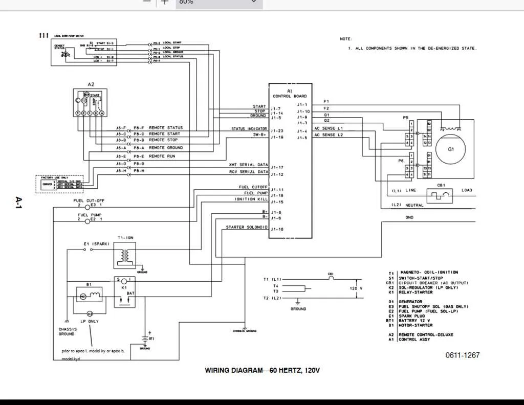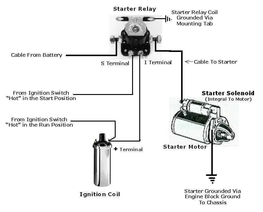
If you’re troubleshooting or installing a power source unit, understanding the electrical layout is essential for proper functioning. To ensure reliable performance, follow the outlined steps to identify each connection point and ensure they’re correctly configured for safe operation. Missing or incorrect links can lead to malfunction, inefficient energy use, or even potential hazards.
Start by carefully inspecting the power input and output circuits. Make sure all wires are properly secured and free from wear. Pay particular attention to grounding points, as a faulty ground can lead to system instability or short circuits. Use a multimeter to test continuity and verify that each circuit is connected as specified in the manual.
The control board should be carefully examined for any signs of wear or damage. Recheck all signal paths and the connection to the starter system to ensure smooth startup and operational flow. Replace any components that appear damaged or corroded to avoid disruption in power transfer.
Finally, always follow the color codes and reference the internal schematic when in doubt. The system’s configuration may differ slightly based on the model, so consulting the manual is a critical step to avoid costly mistakes.
Electrical Connections for Your Power System
Ensure proper connection of the ignition system by confirming that the stator is correctly wired to the control board. Check the voltage regulator’s terminals to ensure consistent output under load. When linking the battery, confirm the positive and negative leads are tightly secured to prevent power loss. Ensure the field coil is properly connected to the rotor for stable output. If a starting circuit is used, verify that the starter motor is connected to the main switch and control module correctly.
Key Connections to Check:
- Stator to Control Board: Verify proper voltage readings across each terminal.
- Regulator to Output: Test for stable output during heavy usage.
- Battery to Power System: Ensure correct polarity and tight connections.
- Field Coil to Rotor: Test continuity for proper operation.
- Starter to Switch and Control Module: Confirm correct wiring for efficient startup.
Test each connection with a multimeter to avoid short circuits and ensure the stability of the system during operation. Properly configure the grounding connections to minimize interference and avoid electrical malfunctions.
Understanding the Basic Electrical Connections

Ensure that all power cables are securely connected to the correct terminals before operating the unit. The main power leads typically connect to the starter motor and the voltage regulator. Check that the battery is properly wired to the unit’s electrical system to provide reliable start-up power. A solid ground connection between the frame and the battery negative terminal is essential for preventing electrical issues.
The field windings should be connected to the excitation system, with proper insulation to avoid short circuits. The stator windings, responsible for generating electricity, must be wired to the voltage regulator to maintain consistent voltage output. Verify that the regulator is correctly wired to adjust the voltage as needed based on load conditions.
Don’t overlook the connection for the circuit breaker, which protects the system from overloads. The breaker should be wired to the output circuit, providing an automatic shutdown in case of an electrical fault. Additionally, ensure that the connections for the control panel, such as the start/stop switch and meter readings, are properly routed to maintain full operational control.
Lastly, confirm that all connections are tight, clean, and free of corrosion to maintain efficient electrical flow and prevent any potential failures during operation.
Step-by-Step Guide to Connecting the Control Panel Circuitry
Ensure the power source is turned off before starting the connection process to avoid any electrical hazards. Begin by identifying the control terminals on the panel, typically labeled for ease of reference.
Start with the main input terminal. Connect the live wire securely to the input port, ensuring a tight fit to prevent any loosening over time. For safety, use a wire gauge that matches the panel’s specifications.
Next, identify the neutral terminal. Attach the neutral wire here, ensuring there is no exposure of the wire, and the connection is firm to prevent corrosion. Ensure that this connection is isolated from any live terminals to prevent electrical shorts.
Proceed to connect the grounding terminal. Use a properly rated ground wire and connect it to the panel’s designated grounding point. The grounding wire should be as short as possible to reduce resistance and improve safety.
For the indicator lights or control switches, match the corresponding wires as per the manufacturer’s manual. Be careful not to cross connections, as this could cause malfunction or failure of the control functions.
Double-check all connections before securing the panel. Tighten all screws and bolts to prevent loosening from vibrations or operational stresses. Ensure that no exposed wiring is left that could cause electrical shocks.
Once all connections are made, test the system by turning the power on and verifying each control function for correct operation. If any issues arise, check the connections again or consult the manufacturer’s troubleshooting guide.
Troubleshooting Common Electrical Issues in Compact Power Units
If your compact power unit is experiencing electrical problems, check the following areas to resolve common issues:
- Check for Loose Connections: Ensure all connections, especially those at the terminals, are tight and free from corrosion. Loose or corroded connections can lead to power loss and overheating.
- Inspect Fuses and Circuit Breakers: A blown fuse or tripped circuit breaker can interrupt the power flow. Replace any blown fuses with the correct type and rating. Reset the breaker if it’s tripped.
- Verify the Control Board: A malfunctioning control board can cause erratic behavior. Ensure all wires leading to the board are properly connected. Look for signs of burnt components or damage.
- Examine the Battery and Charging Circuit: A low or dead battery will affect the unit’s startup. Test the battery voltage and check the charging system for proper operation. Replace the battery if necessary.
- Look for Shorts: Inspect the unit for any short circuits, particularly in areas with exposed wires or near moving parts. Use a multimeter to test continuity and identify any shorted wires.
By following these steps, you can identify and fix most electrical issues without professional assistance. If problems persist, further diagnosis may be needed with advanced tools. Always refer to the manufacturer’s guidelines for detailed troubleshooting procedures specific to your model.