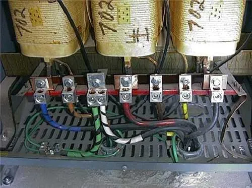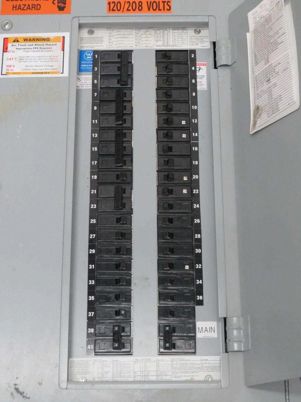
For efficient power distribution, it’s crucial to establish the right connections when stepping down from a high-voltage system to a lower voltage one. The process involves selecting the correct taps and configuring the primary and secondary circuits in accordance with industry standards. First, ensure that the voltage ratios are properly matched by considering the primary voltage input and desired secondary output.
Important considerations include selecting the proper gauge of wire to handle the current load and ensuring that all components are rated for the specific electrical demands. Also, the alignment of the phases and ensuring the correct polarity are fundamental to maintaining system stability.
Start by mapping out the core components and their respective connections. Be sure to maintain proper isolation between the primary and secondary sides, using correct grounding techniques to avoid short circuits or electrical hazards.
Lastly, verify the load capacity and ensure that all safety mechanisms, such as fuses and circuit breakers, are in place. This will safeguard the system against potential faults and prevent overheating or damage to sensitive equipment.
Voltage Conversion Setup: 480V to 208V
To properly connect a high-voltage 480V system to a lower 208V configuration, follow these steps:
- Ensure the primary side is correctly connected to the 480V input, with proper grounding in place.
- The secondary side must be configured to output 208V. Typically, this involves linking the center tap to ground, if required by the setup.
- Utilize the correct wire gauge for both input and output connections, following local code standards.
- Verify the correct polarity when connecting each phase to the system to avoid damage to equipment.
- Install a fuse or circuit breaker rated for 208V on the output side to protect the equipment from overload.
Additional considerations:
- Check the voltage ratings of all connected devices to ensure they can handle the new 208V output.
- Ensure the neutral wire is correctly sized and grounded.
- Test the system after installation with a multimeter to confirm voltage is being properly converted.
How to Connect Primary and Secondary Windings in a 480 to 208 Transformer
To connect the primary and secondary coils, first ensure the supply voltage matches the specifications for the input side. For the primary side, connect the three-phase power lines directly to the appropriate terminals, typically marked L1, L2, and L3. Make sure the phase sequence is correct to avoid reverse rotation issues.
On the secondary side, identify the corresponding terminals for the output voltage. For a standard setup, use the center-tapped neutral to establish a balanced load across the phases. If the secondary requires a different configuration, such as delta or wye, ensure the connections align with your load’s needs.
Verify grounding at both ends of the system. The neutral point on the secondary should be grounded, as it prevents electrical hazards. Ensure the primary side is properly isolated, especially if using fuses or circuit breakers for added safety.
Use appropriate wire gauge for both primary and secondary connections, factoring in current ratings and voltage drop calculations to avoid overheating or potential damage. Check the system under load and confirm voltage output is stable.
Finally, test the system with a multimeter to ensure there are no shorts or irregularities before powering up. Monitoring the system during the first hours of operation will help identify any potential issues early.
Step-by-Step Guide for Proper Grounding in High-to-Low Voltage Step-Down Systems
Ensure the primary and secondary neutrals are properly bonded to the ground system. This establishes a solid reference point for the system’s voltage. Failure to properly connect these could result in hazardous voltage fluctuations.
Begin by connecting the ground terminal of the low-voltage side to an appropriate ground rod or electrode system. The rod should comply with local electrical codes and provide a low-resistance path to earth. This reduces the potential risk of electric shock.
Use a copper wire of adequate gauge to link the system’s ground to the grounding electrode. The wire should be continuous and free from any splices, as this ensures a reliable, low-resistance path. A ground loop can occur if there is any interruption or weakness in this connection.
The ground conductor on the high-voltage side must be equally effective. Be sure the neutral is effectively grounded, which prevents excessive voltage from building up in case of faults. The integrity of this connection will directly influence system stability.
Install grounding at each accessible point of the secondary system, including distribution panels and other equipment connected to the lower-voltage circuit. It is crucial to minimize the distance between the ground connection and each piece of equipment to avoid potential ground faults.
Inspect all grounding connections regularly for corrosion, especially in areas subject to moisture or outdoor environments. Replace any corroded or loose connections immediately to maintain safe operation.
Lastly, implement a proper grounding test to verify that the system provides the desired level of protection. A low-resistance meter can be used to ensure the connection complies with safety standards.
Common Mistakes to Avoid When Installing a Step-Down Unit

Incorrect connection of primary and secondary windings is one of the most frequent errors. Always double-check the label for correct orientation to avoid potential short circuits or improper voltage distribution. Make sure the primary side is connected to the higher voltage source and the secondary side to the lower voltage load, ensuring proper operation of the step-down system.
Overloading the secondary side can lead to overheating and failure. Ensure that the total wattage of the connected equipment does not exceed the rated capacity of the secondary side. Calculate the required amperage and verify that your setup adheres to these limits.
Using improper wire gauge for the high-voltage side is another common mistake. Using wires that are too thin can result in voltage drops, overheating, and potential fire hazards. Always use the correct gauge as specified for high-voltage connections.
Failure to ground the system properly can result in electrical shock or damage. Always ensure a solid grounding connection for both safety and equipment protection. A poor grounding setup can cause erratic behavior and equipment failure.
Neglecting to check the polarity when connecting leads can lead to malfunction. Ensure that the connections follow the polarity guidelines provided by the manufacturer to avoid reversed phases, which can damage both the equipment and the power system.
Improper fuse or breaker selection can cause inefficiency and risk. Choose fuses or circuit breakers that are rated for the specific load of the secondary side. Incorrect protection devices can either fail to protect during an overload or trip unnecessarily during normal operation.
Skipping insulation and protection for exposed connections can expose the system to external damage or accidental contact. Always use appropriate insulation materials and protective covers for exposed terminals and conductors to ensure long-term reliability and safety.