If you’re working with a 5-terminal setup for a vehicle’s electrical system, understanding the correct placement of each wire is crucial for proper functionality. Each terminal serves a specific purpose, and miswiring can lead to malfunctions or even damage to components. Here’s a clear guide to help you get the connections right from the start.
First, locate the main power source and ensure it’s properly grounded. The initial connection should be the one that provides energy when the system is activated. This wire will usually be linked to a power supply that feeds into the central control module. Ensure this connection is secure and free from corrosion.
The second wire is typically dedicated to activating the relay that powers the engine or system. It should be connected to the part responsible for starting the vehicle, which will allow the system to draw power when necessary. Check the voltage and ensure it matches the recommended specifications to avoid damage.
Next, you’ll need to identify the safety or accessory wire. This one often controls additional systems like lights or other features that only operate when the vehicle is in a certain state. Be mindful of any accessory settings and ensure they are correctly configured to avoid short circuits.
Lastly, a couple of connections are dedicated to auxiliary operations, such as turning on certain sensors or systems during operation. These wires should be routed to their respective components. Incorrect wiring here can result in inconsistent performance or failure of essential systems.
Remember, each wire’s role is critical to the vehicle’s overall functionality. Double-check your connections and refer to a reliable schematic to ensure everything is wired correctly before powering up.
5 Terminal Starter Circuit Setup
For proper connection, start by identifying the five terminals that need to be linked. Typically, the terminals include power input, accessory output, starter output, and two for neutral or ground connections. The power input will usually come from the battery and should be securely connected to the main feed terminal. Next, the accessory output is often linked to the fuse panel or to devices that require low voltage during operation.
The starter output terminal needs to be connected directly to the starter motor solenoid for activation. The remaining two terminals serve various functions depending on the vehicle’s design. One is typically for grounding, while the other ensures proper functioning of the system’s neutral safety feature. Always double-check the function of each terminal based on your specific model’s requirements to avoid miswiring.
Before completing the setup, ensure that all connections are clean and free of corrosion to prevent potential issues with power flow. After confirming the connections, test the system by engaging the unit in its normal operating sequence. If the system fails to engage or shows signs of irregularity, retrace your connections and check for shorts or loose terminals.
Understanding the Function of Each Connector in a 5-Pole Electrical Key Mechanism

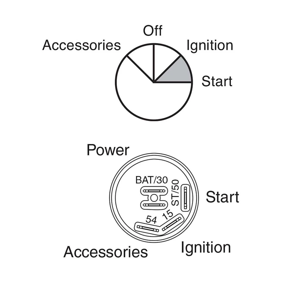
The first terminal is responsible for the continuous power supply. It connects directly to the battery and ensures that the device remains powered even when the key is in the off position.
The second contact is used to activate the primary circuits, sending current to essential systems when the device is turned to the first position. This typically engages basic electrical components, such as lights or a dashboard indicator.
The third terminal activates the starter motor. Upon turning the key, this connector directs a current to the starter relay, engaging the engine cranking process.
The fourth terminal is often linked to auxiliary functions, such as powering accessories or other minor components. It allows users to operate non-essential systems independently from the main engine functions.
The final connector completes the circuit when the key is fully rotated, often enabling the fuel pump or activating security features. This ensures the proper initiation of engine-related processes and may serve as an additional safety mechanism.
Step-by-Step Guide to Wiring a 5 Pin Ignition Switch

Start by identifying the terminals. The first terminal is usually for the battery’s positive connection. Secure the cable from the battery’s positive terminal to this connection. The second terminal is meant for the starter relay or motor, which triggers engine operation when engaged. Connect the wire leading to the starter motor here.
Next, locate the third terminal, which is for the accessory power. This is the wire responsible for powering lights, radio, and other accessories. It connects to the accessory relay or fuse block, depending on your system.
The fourth connection is often for the ground. Ensure that the negative lead from the battery is firmly attached to this point. This creates the necessary return path for the current to flow.
Finally, the fifth terminal is for the primary circuit that enables the vehicle to run once the system is active. This is where the main power feed to the vehicle’s electrical system should connect, ensuring the operation of essential functions like the fuel pump or ECU.
After securing the wires, double-check each connection for tightness and ensure no bare wires are exposed to prevent short circuits. Once everything is properly in place, perform a test to confirm the system powers on and functions as expected.
Troubleshooting Common Issues with 5 Terminal Electrical Connections

If your vehicle fails to start or experiences intermittent power issues, the most common culprit could be related to the connection of the terminals. Here’s how to identify and resolve typical problems:
- Power Interruption: Check for a loose or corroded connection on the terminal responsible for the main power feed. Inspect for any signs of wear on the wire and ensure it securely connects to the battery.
- Starter Engagement Failure: If the engine doesn’t turn over, ensure the connection leading to the starter solenoid is intact. This is the terminal that bridges power from the battery to the starter motor.
- Accessory Malfunctions: If accessories aren’t functioning properly, the terminal responsible for providing power to auxiliary systems might be faulty. Test with a multimeter to ensure it’s supplying the correct voltage.
- No Response When Turning the Key: This could be due to an issue with the terminal that communicates with the control circuit. Check for any faults or breaks in the connection.
- Frequent Blown Fuses: Overloading can occur if a terminal that handles high-current loads is damaged or miswired. Inspect the circuit for any shorts or signs of overheating.
For best results, always ensure you’re using a clean, properly functioning contact. Use dielectric grease to prevent corrosion and maintain a strong electrical flow.