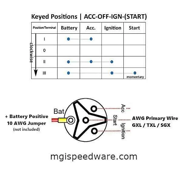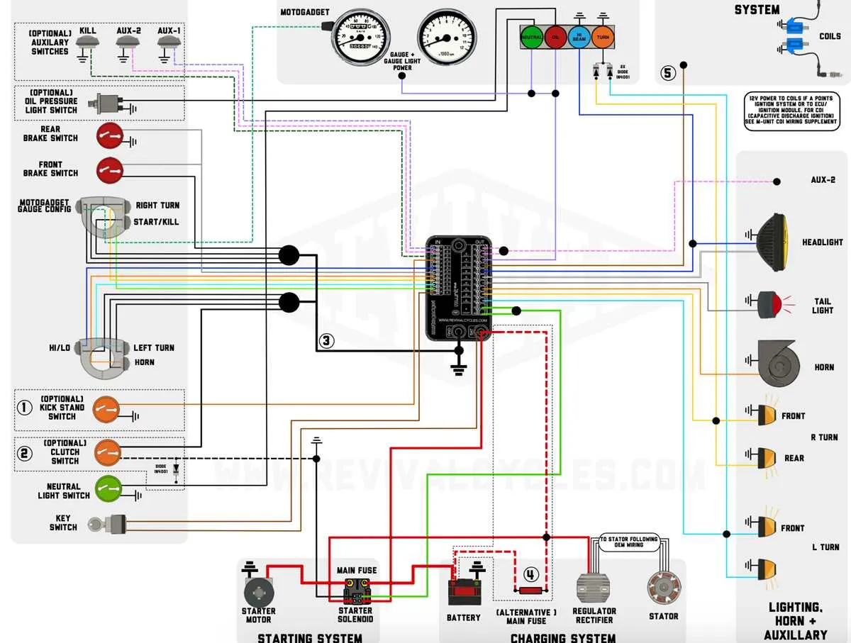
For reliable integration of a versatile engine start controller, ensure you identify the primary power feed, starter relay trigger, and accessory circuits precisely. Use a 12V stable source rated for at least 15 amps to avoid voltage drops that can cause intermittent operation or failure.
Pin configuration varies depending on the model, but typical terminals include constant battery input, ignition feed, starter activation output, and a ground. Confirm each wire with a multimeter before final attachment to prevent damage to the vehicle’s electrical system.
Employ fused connections on all power inputs and outputs to protect against shorts or overloads. Follow manufacturer color codes when available, or refer to standard automotive color conventions: red for constant power, yellow for starter feed, and brown or black for ground.
Connection Scheme for a Multi-Brand Engine Start Control
To ensure correct installation of a generic engine start controller, connect the main power input (usually red) directly to a constant 12V source with a proper fuse rated at 15A. The ignition feed line (often brown or yellow) should link to the accessory circuit to energize when the key is turned on.
Grounding must be solid and attached to the chassis or negative terminal to avoid erratic operation. The starter wire (typically blue) connects to the starter solenoid input to engage the motor when the key reaches the start position.
For added safety, incorporate an inline fuse on the starter lead. If present, connect the illumination wire to the vehicle’s dashboard lighting circuit for backlighting functionality during night operation.
Confirm the terminal designations on the controller body match the vehicle’s system before making connections. Use crimp connectors or solder joints with heat shrink tubing to secure each link and prevent corrosion or disconnection.
How to Identify and Connect Ignition Switch Terminals
Locate the terminal labels first: Most control units feature stamped or printed letters such as B (battery), IG (ignition), ST (starter), and ACC (accessory). Use a multimeter to verify continuity between the power source and these contacts.
Confirm the power input terminal: The terminal marked B or BAT connects directly to the battery positive line. Ensure this is fused properly before attaching the main feed.
Identify the crank terminal: The ST contact activates the starter solenoid. This wire only receives power during engine start, so test by turning the key to the start position and checking voltage output here.
Locate accessory feed: The ACC terminal powers devices like the radio or dashboard lights. This output should have voltage only in the “on” and “accessory” key positions.
Connect the ignition line: The IG terminal supplies voltage when the engine runs. Connect this to the coil or ignition module input to maintain power once started.
Use proper gauge wires: Match cable thickness to the current requirements for each terminal to avoid voltage drop or overheating.
Verify with a continuity test: After all connections, test each terminal against its corresponding circuit to ensure correct installation and avoid shorts.
Step-by-Step Guide to Connecting a Vehicle’s Starter Control

Begin by disconnecting the battery to prevent electrical shorts. Identify the main power lead from the battery; connect this to the terminal marked for constant voltage input. Next, locate the accessory output terminal and attach the wire leading to the vehicle’s auxiliary systems such as the radio and dashboard lights.
Find the ignition feed terminal and link it with the cable responsible for activating the engine’s fuel and spark systems. Then, connect the starter solenoid wire to the designated starter terminal on the control unit, ensuring a secure fit for reliable engine engagement.
Ground the assembly by attaching the negative wire to a clean, bare metal surface on the vehicle chassis. Double-check all connections for tightness and correct placement. Finally, restore battery power and test the unit by turning the key or activating the start mechanism to verify proper operation of all electrical circuits involved.
Troubleshooting Common Connection Issues with Multi-Model Start Controls

Always begin by verifying continuity and proper voltage at each terminal before further diagnostics.
-
No Power to the Control:
- Check fuse integrity related to the starter circuit; replace blown fuses immediately.
- Ensure battery terminals are clean and tight, providing stable current flow.
- Inspect main harness connectors for corrosion or bent pins interrupting power delivery.
-
Starter Does Not Engage:
- Test output terminal for activation voltage when key is turned; absence indicates faulty actuator or wiring break.
- Verify neutral safety or clutch interlock switches aren’t preventing signal transmission.
- Look for damaged ground connections that can cause incomplete circuits.
-
Intermittent Operation or Power Loss:
- Inspect all splices and crimps for loose or oxidized contacts causing signal dropouts.
- Use a multimeter to check for voltage drops exceeding 0.5V across terminals during activation.
- Confirm all cables have proper insulation and no visible chafing or breaks.
-
Accessory or Ignition Positions Not Functioning:
- Test each auxiliary output for correct voltage; missing power indicates internal switch failure.
- Review connections at the relay and fuse box to rule out auxiliary circuit faults.
Use pinout references specific to your control model to verify terminal assignments and signal flow. Replace damaged components immediately to avoid system failures.