For a seamless connection and reliable electrical functionality in your 1967-1972 Chevrolet pickup, ensure you understand the proper placement of wires and the correct power flow. Proper installation of components like lights, gauges, and ignition is crucial for optimal vehicle performance. Begin by referencing the color-coded power routes and connectors specific to this model year. Knowing these details will save you time and potential troubleshooting later.
Start with the ignition system. The key to a successful setup is ensuring that the ignition switch is correctly connected to the fuse panel. If not done properly, your truck may fail to start or experience erratic electrical behavior. Be sure to verify each connection from the ignition switch to the starter relay and to the battery. This will prevent issues such as a lack of power or intermittent starting problems.
Next, check the connections for the dashboard gauges. Each gauge–fuel, oil, and temperature–requires a direct link to the appropriate sensors and power supply. If you’re upgrading or replacing parts, ensure that each wire has the right voltage and resistance for its respective gauge. Missing or faulty connections can result in inaccurate readings, potentially leading to poor maintenance decisions.
Additionally, pay attention to the tail light and brake light circuits. If you find that the rear lights are dim or non-functional, inspect the connections carefully, as well as the ground wire. A loose or corroded ground connection can often be the culprit in such cases.
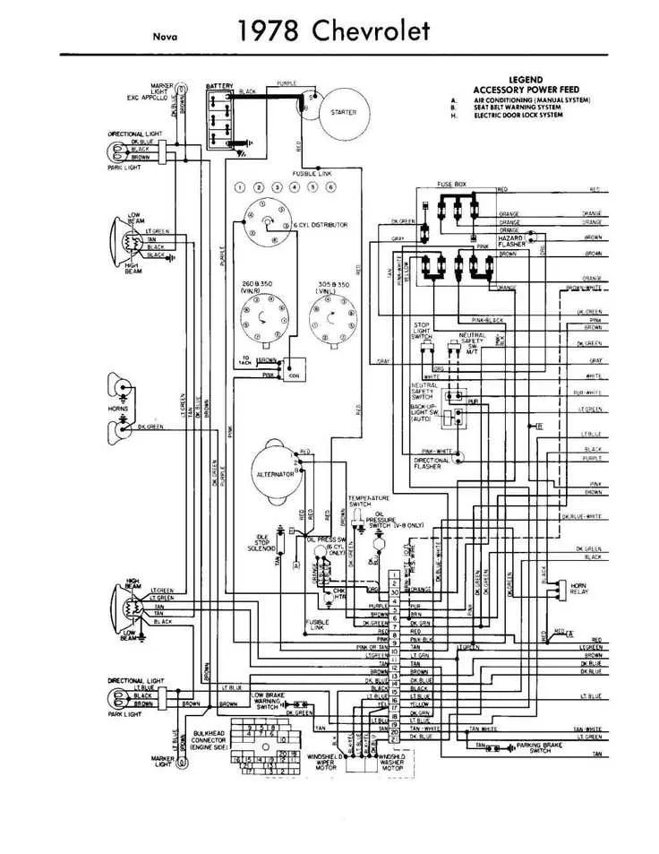
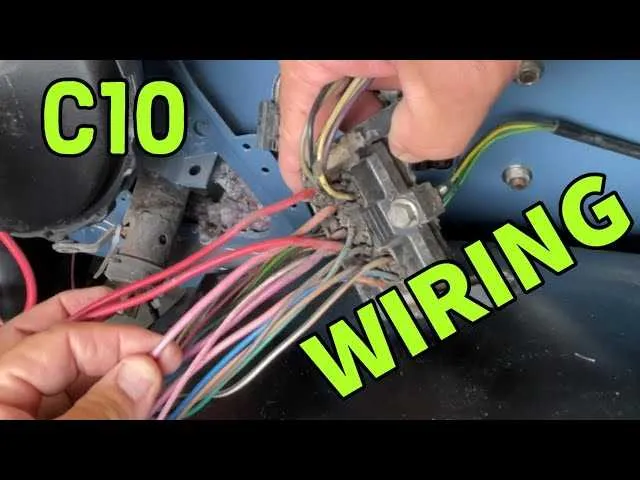
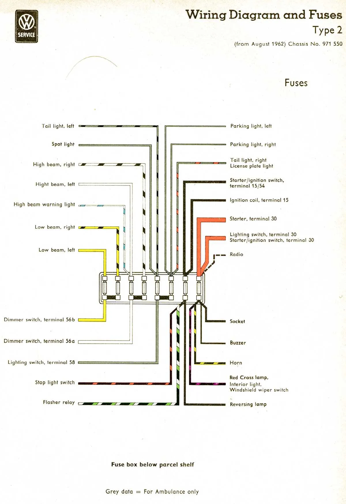
67-72 C10 Electrical System Layout
For owners and restorers of 1967-1972 Chevy trucks, proper understanding of the electrical system setup is crucial for maintenance or upgrades. The following points outline key areas to focus on:
- Ensure the main fuse block is correctly wired to prevent electrical shorts. A faulty connection here can disrupt power distribution.
- The alternator should be wired directly to the battery through a heavy gauge wire to ensure proper charging. Check the connection frequently for wear or corrosion.
- For accurate lighting operation, verify that the headlight circuit is connected to the switch with sufficient gauge wire to avoid dimming or flickering.
- Ensure the ignition system has a reliable power source, especially for early model years where the connection to the coil is prone to issues.
- The ground connections throughout the truck are vital. Inspect the grounding points under the cab and around the engine bay to ensure optimal power flow.
When working with vintage systems, consider replacing old, brittle wires with modern replacements to ensure safety and reliability. Always follow factory manuals for specific wiring details and connections.
- Check the connector block for the instrument cluster to prevent erratic behavior of gauges and lights.
- Be aware of the voltage regulator wiring–incorrectly connected, it can cause fluctuations in voltage, damaging sensitive components.
Proper attention to these areas will ensure your truck remains reliable and safe for everyday use or restoration projects.
Understanding the 67-72 C10 Electrical System Layout
For effective restoration or modification, a clear understanding of the 67-72 C10’s electrical setup is crucial. Start by familiarizing yourself with the main power distribution system, including the fuse block’s location and connections. The fuse block in these models is typically mounted under the dashboard, often on the driver’s side, near the lower part of the dashboard frame. It plays a central role in protecting the vehicle’s electrical components.
Key components to focus on: The ignition switch controls the power supply to the engine and auxiliary circuits, located on the steering column. Ensure that the switch is properly aligned and connected to avoid issues with power interruptions during operation. The headlight switch, typically located on the dash or steering column, connects to the light circuits and should be inspected for wear.
The engine compartment holds critical connections for the alternator, battery, and voltage regulator. Pay particular attention to the alternator’s wiring, as loose or corroded connections here can lead to charging issues. Also, check the ground connections in the engine bay to ensure proper electrical flow.
Next, the interior lighting system should be reviewed. The instrument panel lights, dome lights, and switches often suffer from poor connections over time. These can be traced back to the main harness running along the dashboard. Replacing any worn or damaged connectors will improve the overall reliability of the interior lighting system.
Lastly, pay close attention to the tail light and brake light assemblies. The wiring in these areas is prone to corrosion due to exposure to the elements. Ensuring a solid connection at the rear of the vehicle will prevent issues with lighting functions.
For troubleshooting, use a multimeter to test voltage at key points, such as the battery, fuse block, and alternator connections. It’s essential to have a reliable electrical layout reference to pinpoint faults accurately.
How to Identify and Troubleshoot Common Wiring Issues in the 67-72 C10

Start by inspecting the fuses. Many electrical faults stem from blown fuses. Replace any that are damaged or show signs of wear. Always use the correct amperage to prevent future issues.
Check for visible damage to the insulation. Exposed or frayed wires often cause shorts or intermittent electrical problems. Cut out the damaged section, strip back the insulation, and reconnect using appropriate connectors.
Test the grounds. Poor grounding is a frequent cause of malfunctioning electrical systems. Ensure all ground connections are clean, tight, and free of corrosion. If necessary, scrape the contact points to ensure a solid connection.
Look for loose or corroded connectors. Loose connections can lead to unreliable power delivery. Inspect all connectors for tightness, corrosion, or rust. Use a dielectric grease to protect the connections from moisture and corrosion.
Verify the power supply to key components. If parts of the vehicle aren’t receiving power, it could be due to faulty relays or wiring faults between the battery and those components. Use a multimeter to check for voltage at the source and along the path.
Test the switches and sensors. Faulty switches, including the ignition or light switches, can stop circuits from operating. Check continuity with a multimeter to identify any problems.
Inspect the connectors for the ignition system. Poor connections here often lead to starting issues. Ensure that the terminals are clean, corrosion-free, and making proper contact.
Check for voltage drops. A voltage drop across a connection could indicate a resistance issue, such as a loose or corroded terminal. Use a voltmeter to identify where the voltage is being lost.
Look out for intermittent issues. Sometimes, electrical problems are intermittent and difficult to track. Wiggle wires or connectors while monitoring the system for any changes. This can help you locate the faulty connection.
Ensure proper fuse and relay operation. Fuses and relays often wear out over time. Use a multimeter to test for continuity and replace any faulty components.
Step-by-Step Guide to Wiring the 67-72 C10 for Custom Mods

Start with Disconnecting the Battery: Before beginning any electrical modifications, always disconnect the battery to prevent accidental short circuits and ensure safety while working on the electrical system.
Remove Old Wiring Components: Take out any obsolete wires or connectors that won’t be part of your new setup. This includes factory harnesses or unused circuits that may interfere with your custom build.
Identify Power Sources: Find your vehicle’s main power feed and ignition switch circuit. The power feed is usually located in the fuse box area. It’s essential to identify and plan the routing of power lines for accessories and mods.
Install New Switches and Relays: Install custom switches, relays, and circuit breakers where necessary for mods such as upgraded lighting, electric fans, or aftermarket components. Make sure to use heavy-duty relays for high-power devices.
Ground Connections: For all electrical systems, ensure solid ground connections. A poor ground can lead to voltage drops or malfunctioning of your components. Clean off any rust or debris at the ground points before installation.
Fuse Protection: Always protect modified circuits with appropriate fuse sizes. Check the amperage rating of each mod and use fuses rated slightly higher than the required draw, but not excessively high.
Route Wires Neatly: Run the new wires along the chassis in a way that keeps them secure, away from heat sources, and free from potential abrasion points. Use protective wire loom or rubber grommets at holes to prevent chafing.
Connect Power to Accessories: Powering accessories such as lights, radios, and other aftermarket parts should be done through properly rated relays and switches to ensure reliability and safety.
Test Each Circuit: After installation, perform a complete system check. Turn on each accessory and verify that all connections are solid, no wires are shorting, and there’s no excessive heat buildup.
Reinstall Battery: Once all wiring is complete, reconnect the battery. Test the electrical system thoroughly to ensure everything is working as intended and there are no issues with power delivery.