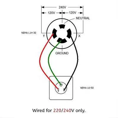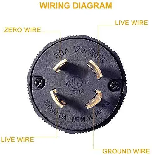
For a reliable connection, ensure that the power supply is routed through a 4-prong receptacle, where the ground pin is properly connected to the grounding system. This setup prevents potential short circuits and ensures safety under high voltage conditions.
The neutral wire should be clearly separated from the ground to avoid electrical faults. Proper installation requires that the neutral conductor is tied to the central bus bar in the main service panel. This prevents issues such as electric shock or fire due to improper grounding.
Before proceeding, double-check that each terminal is tightened securely, particularly the hot wires, to prevent overheating or power loss. Incorrect wire placement or loose connections can lead to malfunctioning appliances and safety hazards. Be sure to follow local building codes for accurate installation and testing.
Electrical Connection for 30 Amp Twist-Lock Plug
For proper installation, ensure the power source and plug connector are rated for 30 amps. The black wire should be connected to the brass terminal, while the white wire connects to the silver terminal. The green or bare copper wire attaches to the ground terminal. Verify the conductor gauge matches the amperage–use 10 AWG for this type of circuit.
Before proceeding, double-check the color coding for each wire and confirm all terminals are secure. This type of plug features a twist-lock mechanism, ensuring a secure connection. Avoid over-tightening, as it can damage the components. Make sure the plug is compatible with the equipment to avoid overload risks.
When wiring a 240V circuit, ensure that the power is turned off before making any connections. A correctly wired setup will reduce the risk of electrical faults and ensure safety when using high-power appliances.
Understanding the Components of Electrical Connection Design

When working with an electrical setup featuring a 240V plug with 3-phase power, it’s crucial to understand the roles of each part involved. Proper comprehension ensures safety and functionality in any installation. Below are the main components that must be correctly configured for efficient operation.
- Neutral Wire: This is essential for balancing the system. It provides a return path for current, which is critical for stabilizing voltage across the system.
- Hot Wires (Live Wires): Typically, there are two or three hot wires. Each supplies current from the power source to the device. Ensuring proper phase alignment is vital for achieving balanced load distribution.
- Ground Wire: This wire provides a safe route for electricity to flow into the earth in case of a fault. It prevents electrical shock by directing current away from the user.
- Connection Terminals: Each wire must be securely connected to the correct terminal. Misconnection can cause shorts or unsafe operation. Pay close attention to the layout of terminals, especially when dealing with multiple live wires.
Additionally, ensure all components are rated for the correct amperage and voltage to avoid overheating or failure. Check manufacturer guidelines for specific configurations and safety measures.
Step-by-Step Guide to Wiring L14 30p for Proper Connection

Step 1: Begin by ensuring the power is turned off at the circuit breaker before working with any electrical components. This is essential for safety. Use a voltage tester to verify no current is flowing through the wires.
Step 2: Prepare the connectors and the cable that will link the outlet to the power source. Ensure the cable is rated for the amperage of the circuit you are working with.
Step 3: Strip the insulation off the wire ends, exposing the copper. Use a wire stripper for clean, precise cuts, avoiding any damage to the conductors. Leave enough wire exposed for easy connection.
Step 4: Connect the ground wire (usually green or bare copper) to the ground terminal. Secure it tightly to ensure a solid connection.
Step 5: Attach the neutral wire (white) to the neutral terminal, making sure the connection is firm and secure. This wire is crucial for completing the circuit.
Step 6: Connect the two hot wires (typically black and red) to the corresponding hot terminals. These wires are responsible for delivering the power to your device. Be sure to tighten each connection properly to prevent any loose wiring that could lead to arcing.
Step 7: Double-check all the connections for tightness and correct placement. Ensure no exposed copper is visible at the terminal connections.
Step 8: Attach the cover plate to the outlet, securing it with screws to prevent any accidental contact with the wires.
Step 9: Once all connections are made, turn the power back on at the breaker. Use a voltage tester to verify that the device is receiving power and functioning correctly.
Step 10: Always follow local electrical codes and consult a licensed electrician if you are unsure about any step of the process. Safety should always be your top priority.
Troubleshooting Common Issues with 30 Amp Plug Setup
Ensure correct connections by verifying that the neutral wire is not connected to the ground terminal. A faulty connection can lead to electric shocks or equipment malfunctions.
If the system fails to power on, check for a tripped circuit breaker. Reset the breaker and inspect the cable for any visible damage or wear that could be causing a short circuit.
Incorrect polarity between hot and neutral can prevent proper operation of appliances. Use a multimeter to verify that the hot wire is connected to the correct terminal and that the neutral wire is properly grounded.
Loose connections can cause overheating or inconsistent power supply. Tighten all terminal screws securely and ensure that the wires are fully inserted into their respective terminals without fraying or exposure.
For outdoor setups, check for signs of moisture buildup or corrosion at the terminals. Moisture can cause rust, leading to poor conductivity. If found, clean the connectors and apply dielectric grease to prevent future issues.
If you experience frequent tripping or blown fuses, the load on the circuit may exceed its rating. Recalculate the wattage requirement of your connected devices and reduce the load accordingly to avoid overloading.
Lastly, test the functionality of the plug by connecting it to a known working power source. If the system still does not work, the plug or receptacle itself may be faulty and need replacement.