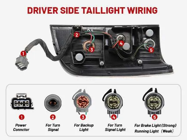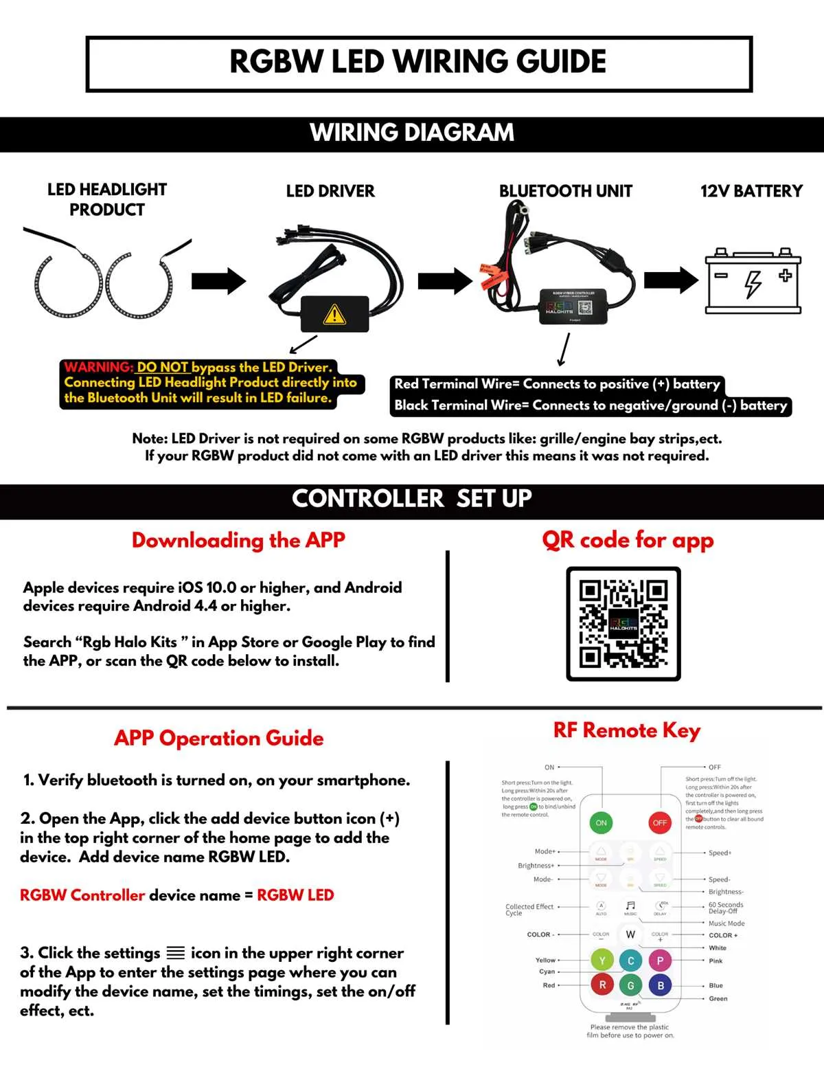
Direct advice: when troubleshooting rear illumination on a 1999 model, begin by inspecting the brown wire leading from the multifunction switch; this conductor supplies voltage to the rear position lamps. Check for continuity and confirm the presence of 12V when the headlamp switch is engaged.
The rear harness includes connections for stop, turn, and marker lamps. Focus on the ground points, particularly G401, located on the left frame rail near the rear bumper. Poor grounding frequently causes intermittent lamp function. Use a multimeter to verify near-zero resistance between the socket ground and chassis.
Color coding is key: brown for tail lamps, yellow for left turn, dark green for right turn, and light green for backup. Trace these circuits from the fuse block to the rear junction connector under the vehicle. Pay special attention to the underhood fuse panel where the park lamp fuse (15A) provides upstream protection.
For splicing or repairs, use weatherproof connectors and ensure proper routing away from heat sources and moving components. Accessing the rear lamp assemblies requires removal of the inner trim panel; retain all fasteners to avoid rattles or reassembly issues.
99 Cadillac Front Marker Circuit Layout
Check the amber marker illumination circuit by locating the brown power feed wire entering the front assembly; it typically connects to the parking lamp harness. Ensure the ground wire, often black, is secured tightly to the chassis near the radiator support. Use a multimeter to confirm 12V presence when the headlamp switch is in the parking or headlamp position.
Trace the power route from the under-hood fuse box; inspect the exterior lamp fuse (usually 15A) for continuity. Verify the headlamp switch sends signal voltage through the brown lead when activated. Corrosion at connectors near the front bumper can disrupt current flow, so apply dielectric grease after cleaning.
If troubleshooting the rear, locate the brown wire at the tail section; it’s typically spliced into the rear marker harness. Confirm the chassis ground near the left rear frame rail is clean and secure. Inspect all splices for wear, especially where the harness bends around metal brackets.
For replacements, match bulb type 194 or 168 for front and rear small-marker units. Always check socket condition, as heat can deform plastic housings, leading to poor electrical contact. Re-seat connectors firmly after any repair, ensuring locking tabs click into place.
Connector Pinout and Wire Color Identification for 99 Escalade Running Lights

Refer directly to the underhood junction block. Use a multimeter to verify pin functions before making any connections.
- Connector Type: 4-pin rectangular plug located behind the front fascia, near the headlamp housing.
- Pin 1: Brown wire – provides 12V feed for marker illumination.
- Pin 2: Black wire – ground reference; connects to chassis point behind the left fender.
- Pin 3: Light blue wire – feeds parking beam; controlled through headlamp switch.
- Pin 4: Yellow wire – turns on side marker when directional is active.
Double-check wire colors at the splice points inside the loom, as color fading or aftermarket repairs can alter appearances. Always test continuity back to the switch and fuse panel before finalizing repairs.
- Inspect the inline fuse holder near the battery; use a 15A fuse for proper circuit protection.
- Trace the black ground wire to confirm secure chassis bonding; corrosion here often leads to intermittent failures.
- Measure voltage at the brown lead with the parking beam switch activated; expect consistent 12–14V.
- If signal is absent at the yellow lead, check the turn signal flasher module for proper operation.
Label connectors with tape during disassembly to prevent cross-connection during reassembly.
Step-by-Step Guide to Tracing and Testing the Circuit
Start by disconnecting the negative battery terminal to avoid short circuits. Locate the front marker assemblies behind the grille; use a multimeter to check for 12V at the connector when the switch is activated.
Follow the harness from the front assemblies along the fender well; inspect for damaged insulation or corroded splices. Use a probe to test continuity between the harness connector and the rear marker assemblies.
Access the rear assemblies through the inner panel; remove the connector and test for ground on the chassis side. If no ground is detected, trace the ground path back to the frame attachment point near the rear bumper.
Move to the fuse panel under the dash; check the fuse labeled “PARK LAMP” with a test light. Ensure power is present on both sides of the fuse when the switch is on. Replace any blown fuse with a unit matching the specified amperage.
Locate the headlamp switch; back-probe the output terminal with the switch engaged. Confirm voltage presence; if missing, the switch may require replacement. Check the feed wire from the switch to the harness connector at the firewall grommet.
Inspect the relay box near the battery; identify the park lamp relay. Remove the relay, jumper terminals 30 and 87, and observe if the markers illuminate. If they light up, suspect relay failure; replace if necessary.
Reassemble all connectors and secure harness routes with zip ties. Reconnect the battery terminal, activate the switch, and perform a final visual check of all marker assemblies to confirm consistent illumination.
Common Wiring Faults and Fixes in 99 Escalade Running Light System
Check the brown power lead at the headlamp switch; corrosion at the connector often interrupts voltage flow. Clean terminals with contact cleaner and apply dielectric grease before reconnecting.
Inspect ground points near the front fender; loose or oxidized ground screws frequently cause intermittent illumination. Tighten or replace screws and sand contact surfaces to bare metal.
Trace the circuit to the multifunction switch; worn internal contacts can disrupt the signal path. Replace the switch assembly if continuity tests fail between input and output terminals.
Examine the fuse block under the dash for blown fuses or heat-damaged slots. Replace faulty fuses with the correct 15A rating and clean terminals using a small brass brush to restore connection integrity.
Look for chafed harness sections along the front bumper where vibration causes insulation wear. Wrap exposed conductors with high-quality electrical tape or install heat-shrink tubing for durable repair.
Verify bulb sockets for melted plastic or weakened spring tension, which prevents firm contact. Replace damaged sockets and ensure the replacement units match the original pin configuration.
Use a multimeter to confirm voltage at the rear junction block; low readings often indicate a failing relay. Swap in a tested relay from a matching circuit to verify before purchasing new parts.
Check the splice points inside the harness loom near the firewall; factory splices sometimes develop resistance over time. Cut back the affected section, solder a fresh joint, and seal with heat-shrink for long-term reliability.